


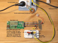

A proprietary very simple, cheap and compact isolated ultra-low power supply circuit with a standby consumption in the range of one Milliwatt was designed last year and with an experimental setup it showed up to 0.8 Milliwatt power output supplying a low energy CMOS microcontroller monitoring and displaying the power consumption of an electric heater on a double 4 digit LCD for demonstration. Apart from powering intelligent sensors, probably the most interesting application of this circuit should be to provide a minimal loss low standby power for monitoring and wake-up of bigger consumer electronics AC power supplies and charger adaptors as a load demand watchdog circuit. Those energy vampires keep sucking the equivalent output of dozens of Gigawatt powerplants and millions of CO2-tons just in standby, which could now be reduced down to one percent or less of this currently wasted energy, resources and pollution.
The novel circuit is essentially based on a DIAC, which is around since the early 60s as a standard component in AC dimmers, a small pulse transformer as commonly used for dataline isolation and three small capacitors: one losslessly AC-current-limiting high voltage input capacitor and one high voltage charging capacitor on the primary side as well as one output buffering capacitor at the secondary side of the miniature pulse transformer behind a diode bridge rectifier. Optionally a LowDropOut linear voltage regulator could precisely regulate the output voltage and smoothen it's ripple at just a few Microwatts additional power loss. When the charging capacitor is loaded up during the AC-sinewave slope via the AC-current-limiting input capacitor and reaches the DIAC breakdown voltage it dischages repeatedly via the primary pulse transformer winding and the bipolar discharge pulse bursts are rectified out of the secondary winding into the buffer capacitor for the output load as DC power or even load/voltage-regulated by means of the optional linear regulator.
On the UltraLowPower Designer Forum last year where this circuit was first demonstrated the engineering audience was wondering, why over the recent 50 years (since all of these components became available) this simple circuit scheme was never evaluated. The circuit schematic is now registered at the German Patent Office, waiting for investors that would be interested in international patent coverage, evaluation and exploitation. With the recently booming mobile communication and media devices market it becomes ever more important to bring down the standby losses of AC power supplies and charger adaptors besides all the other possible consumer electronics and household appliances and those many new intelligent sensors in residential, commercial and public buldings, that may save additional standby power consumption and timewise load-balanced cost on the average.
EcoStar ratings and EuP directives are asking for less than 10 Milliwatt standby losses of AC power supplies and charger adaptors although even the most complex commercial and conventional implementations not even come close to this low range yet. With this unique circuit scheme it would be a snap to even undershoot these ambitious goals by an order of magnitude at least if required.
-
Awards
-
 2012 Top 100 Entries
Voting
-
ABOUT THE ENTRANT
- Name:Hans Diesing
- Type of entry:individual
- Profession:
- Number of times previously entering contest:never
- Hans's favorite design and analysis tools:TinyCAD, OpenOfficeCALC, LTspice
- Hans's hobbies and activities:energy saving inventions, stereo photography
- Hans belongs to these online communities:Linked-In, Xing
- Hans is inspired by:find energy-saving technologies apart from mainstream solutions
- Software used for this entry:TinyCAD, OpenOfficeCALC
- Patent status:patented