


Powered exoskeleton is a branch in robotics technology which is witnessing a rise in research and development. Its applications range from use in the medical industry to use in the military.
Our project is aimed at building an ExoArm which can be used for rehabilitative purposes and power amplification purposes.
Our research has led to development of a simple rotary hydraulic actuator which can provide the primary desired motion of our limbs (Elbow, Knee) rotation, directly from the pressurized fluid. This simple and unique design facilitates its use in variety of applications, which includes full body exoskeleton. Such actuation system will also be efficient in power amplification for its use in defense applications.
The Hydraulic ExoArm is designed to provide mobility for the elbow joint of the user facilitating the rehabilitation of the temporarily impaired joint. It incorporates sensory systems and control system necessary for making it a closed loop adaptive system.
By designing a circular cylinder housing we have removed the need of multiple linear actuators and ball joints to deliver the same torque requirements. This uniform design can be applied to both our elbows and our knees. This has greatly reduced the need for individual development of actuators for the various joints.
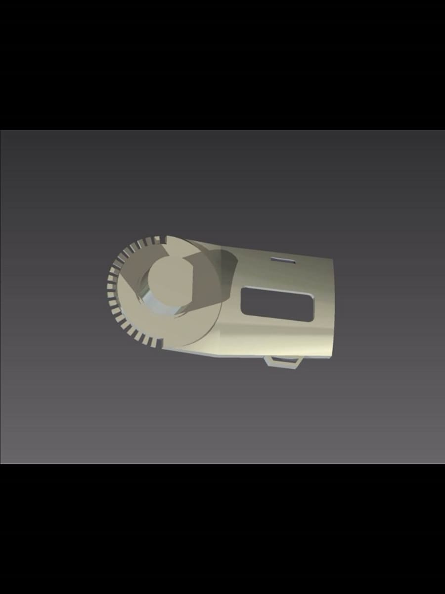
This design of the actuator is a 3-part assembly.
Part Description
The lower part of the actuator assembly is static. The intake of the high pressure fluid is 90 degrees apart. This results in the desired rotation of the forearm and ameliorates the piping of the hydraulic fluid. The pipe system of the fluid can now be either taken perpendicular to the assembly or can be wound along the base of the part. This part has slots along its upper surface for the fitting of the rubber seals. A small shaft at the center acts as a pivot for the rotating surface. The design is such that minimal load occurs at the shaft. Two mechanical stops at the end of either side are built to ensure rotation of the arm within the given range (which is 120 degrees). A central groove is kept to accommodate the Bearing Ring.
The ring part is designed to provide relative motion between the fixed part and the moving part. This ring is a 2 part assembly. Ball bearings will be housed in it and this will be fixed in the grooves of the lower fixed part of the actuator. This will be attached to the base by the means of bolts provided along the circumference of it.
The moving part of the assembly has similar slots like the lower fixed part. This helps to align and seal the parts more accurately. In the center there is a bi-directional surface pivoted along the central shaft. This surface design maximizes the surface area for the hydraulic fluid and reduces the amount of material used for achieving the desired results. Along the edge of its circumference there are round slots provided to fasten bolts joining this part to the static part.
-
Awards
-
 2014 Top 100 Entries
Voting
-
ABOUT THE ENTRANT
- Name:
- Type of entry:teamTeam members:AFZAL AHMED KHAN
RAVIRAJ PRAJAPAT
HARSHIT SAXENA