
In oxygen-free space environments, the power from photovoltaic panels is limited and insufficient to support large-scale engineering projects. Combining a nuclear heat source with an Electronic Carnot Engine (ECE) for power generation could become a critical space technology of the future.
Main Objective
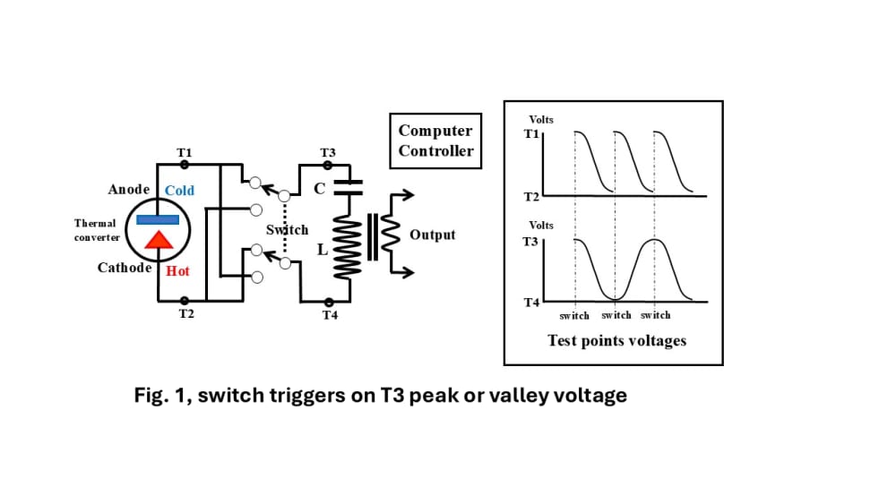
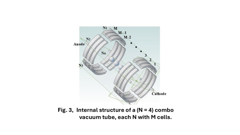
The ECE utilizes following external components:
- An LC resonance tank (resonance cavity)
- Power switches
- A cold source and a heat source
- Control circuits and other accessories (Fig. 1).
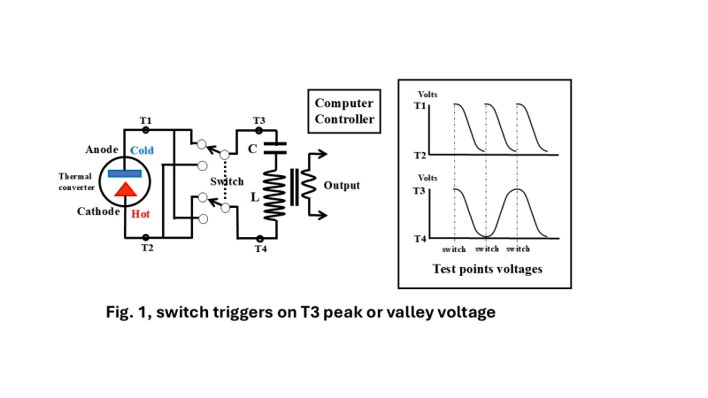
The operating principle of this circuit is simple. Initially, the cathode of the diode is heated to generate thermionic emission, which charges the resonance tank. When the potential at the test point reaches its highest peak, lowest valley, or when the current is zero (as shown by T3 and T4 in Fig. 1), the power switches reverse the connection to the resonance tank. The negative electric field that was just established at the anode is flipped into a positive electric field due to the switching of the resonance tank (as shown by T1 and T2).
When the potential reaches a peak or valley again, the switches reverse once more. This cycle repeats continuously, allowing the resonance tank to rapidly build up an electromotive force (EMF). Once a mature EMF is established in the resonance tank, the control circuit opens a set of secondary coils to output alternating current (AC) via magnetic coupling.
Thermodynamic Analysis
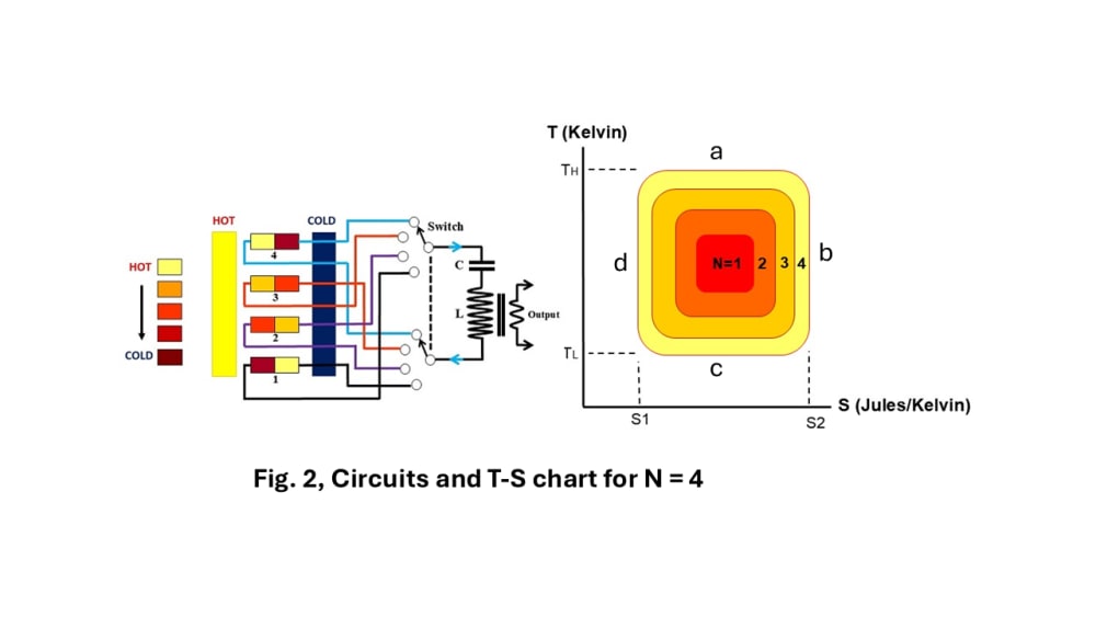
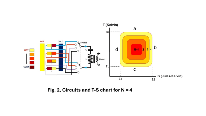
We can analyze the interaction between the diode and the resonance tank from a thermodynamic perspective (Fig. 2):
- Process “a”: Isothermal Expansion.
- Process “b”: Adiabatic Expansion.
- Process “c”: Isothermal Compression.
- Process “d”: Adiabatic Compression.
The sequence described above is precisely a Carnot cycle. According to the definition of entropy, dS = dQ / T. process “a” in Fig. 2 represents the cathode electrons being heated along the high-temperature isotherm
Th. Integrating dS from S1 to S2 yields the thermal energy Q. Through process “b”, creating an EMF that drives the resonance tank and a, b, c, d area is the net work done by the system.
Thermal Resistance and Time-Base Matching
The delay of the thermally conductive thin wall is approximately on the order of milliseconds, which becomes the bottleneck for the isothermal process. In contrast, the heating of the electrons themselves occurs on a nanosecond scale and does not need to be factored in.
Power Generation Efficiency
Calculated according to the Carnot cycle formula (E = 1 - TL / TH), a system with a cathode at 1200°C and an anode at 90°C has an estimated total system efficiency could land around 42%.
Applications
As a direct energy conversion source, the electronic engine can generate power in oxygen-free environments underwater or in space to serve as a power source for Air Independent Propulsion (AIP).
Summary
If entropy change is interpreted as a thermomotive force, then the ECE is a converter that transforms thermomotive force of electrons into electromotive force — just as a diesel engine transforms the thermomotive force of combusting molecules into mechanical work.
Like this entry?
-
About the Entrant
- Name:Kan Cheng
- Type of entry:individual
- Profession:
- Number of times previously entering contest:2
- Kan's favorite design and analysis tools:Alibre cad tool
- Kan's hobbies and activities:Thermal dynamics study
- Kan belongs to these online communities:line
- Kan is inspired by:1. A sustainable environment for future generations.
2. Future powertrain.
3. Green energy. - Software used for this entry:None
- Patent status:none