


This design idea is a speed change mechanism that mainly brings the possibility of high efficiency, than avoiding power losses, usual characteristic of mechanical transmissions. For example in the car industry, the automatic transmission and the associated drivetrain usually consume about 20 percent of the engine's power and a manual transmission takes about 16 percent of the power.
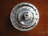
One challenge to using magnets rings instead of steel gears in the transmission is to use as large as possible a magnetic area from each magnet ring to increase torque transmission and then reducing the necessary magnet size. Using magnets rings, as the example in the attached photo, with one first magnet ring with inner poles and one second magnet ring inside the first magnet ring with outside magnet poles makes possible more magnet poles close from both magnet rings to increase the torque transmission. The torque transmission will increase, decreasing the difference of the number of poles between both magnet rings.
Using this idea the present design relates to a speed change mechanism using two epicyclic transmission stages with the torque transmission done between two magnetic poles rings of each stage and the transmission ratio change is done by changing the pairs of magnetic poles rings that are transmitting torque.
It is possible to have one or more pairs of magnetic poles rings in each transmission stage for torque transmission, working one pair or another, or working each pair alternately or working pairs of magnetic poles rings with variation in the number of poles and than to change the transmission ratio is necessary to change the pair of magnetic poles rings transmitting torque. To form the magnetic poles rings can be employed permanent magnets, electromagnets, salient poles of soft magnetic material, etc.
Some advantages of this orbital magnetic speed change mechanism are the possibility of reaching large transmission ratios, high efficiency, great torque transfer, very compact drives, no wear and simple construction.
The orbital magnetic speed change could be used for automotive transmission, wind turbines transmission, machines and others where transmission ratio change is necessary.
The photo attached shows part of one prototype using permanent magnets (19 X 12,6 X 6,3 mm of NdFeBr) where there are 14 magnets in the internal pole ring with orbital and rotational motion and 16 magnets in the external fixed ring ( external housing diameter is 100 mm ) with the torque transmission about 13,6 Nm between the magnet rings.
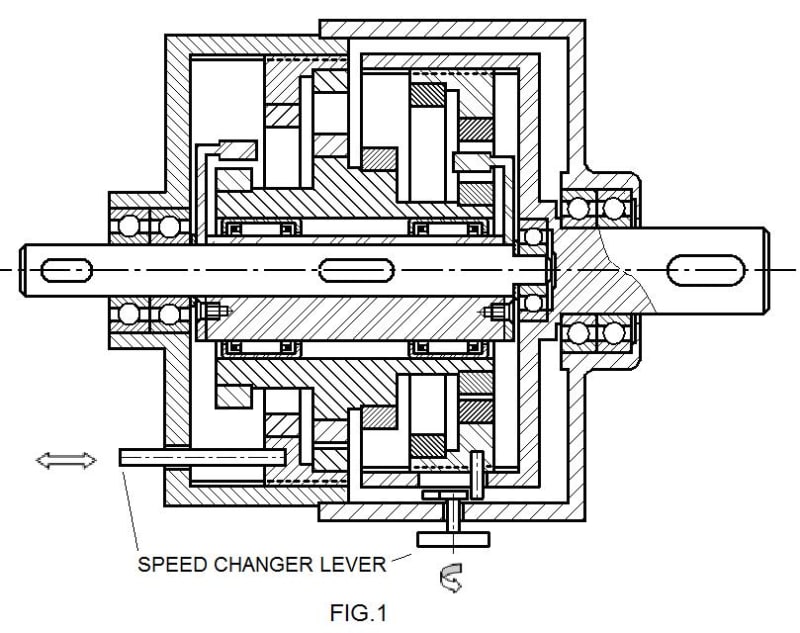
FIG. 1 presents a longitudinal section view of an orbital magnetic speed change with all magnetic poles rings formed by permanent magnets and the two external magnet poles rings of the first and second stages being each set mounted in a support with axial movement in its base.
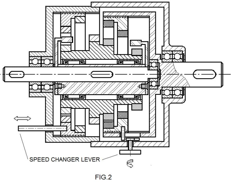
FIG. 2 presents the orbital magnetic speed change of FIG. 1 with the two supports of the magnetic poles rings, displaced axially resulting in other transmission ratio.
The design shown is for easy understanding, but many other design for the orbital magnet speed change are possible.
Like this entry?
-
About the Entrant
- Name:Valmor Gravio
- Type of entry:individual
- Software used for this entry:M.S. Paint
- Patent status:patented