


For 30 years lean combustion has been known to lower NOx emissions and many programs outline its benefit and in its Tapps II Combusor final report submitted by GE for its GEnx Engine in 2013 it shows zero fractal components. If things are the same, a small but important change can be made. It was shown that fractal grids can increase turbulence by over 100% and higher (Geipel et al 2010). In the recent book “Fractal Flow Design: How to Design Bespoke Turbulence and Why” Springer 2016. Editors Yaschiko Sakai and Christos Vassilicos outlined a series of studies that show bespoke or “customized” turbulence is now possible and can play an important role in Lean Combustion.
A lean burn combustion system reduces the flame temperature. Lean means that you have more air than is required to burn fully the injected fuel. Therefore, you burn fuel with air and then you have air remaining that will absorb the generated heat and as a consequence the overall gas temperature is lower than the flame temperature. This reduction of the temperature reduces NOx emissions.
The fuel is injected separately from the air stream in order to have premixed burning, you need to mix the air and the fuel streams quickly close to the burner exit.
Increased turbulence helps mixing and fractal grids deliver high turbulence and faster mixing between fuel and air. Which as we know benefits by lower flame temperature which reduces NOx emissions.
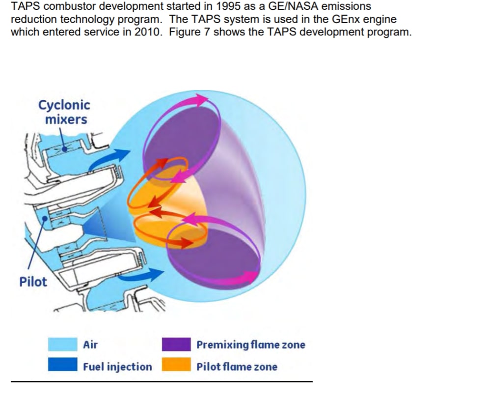
We estimate an overall reduction of NOx by 10% and particulates even more and an improvement in efficiency 2-3%. Too see a visual example of the quality of the mixing the attached #1 chart show the DNS analysis of instantaneous flow fields near the grids: a biplane grid, b composite grid, c fractal grid. Planes show velocity and pressure profiles, graph taken from pp 60 of book.
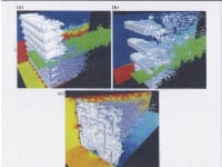
To introduce Multiscale/fractal generated turbulence fractal grids can be introduced inside the air path through the cyclonic mixer and then also around the pilot injection system in the middle.
That’s it! Changing the shape of the orifice can increase turbulence by 100% and higher, (Geipel et al 2010).
See attached #2 image taken from page 12 of the Tapps II final report. if you look on page 12 of the report, you want to introduce fractal grids inside the air path that goes through the cyclonic mixers and at a location upstream of the liquid fuel injection, which is where the blue arrow is. This air path is annular and axisymmetric. Another place where fractal grids can be introduced is at the two air streams around the pilot injection system in the middle. In addition, it may be a fractal design can be used instead of or in addition to the cyclonic mixer. Also the potential exists for the air path inside the burner but less information was given on the details.
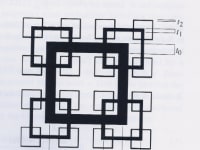
The attached #3 drawing shows a fractal grid with a 65% blockage ratio patent protected US9278362.
Like this entry?
-
About the Entrant
- Name:Theo Wells
- Type of entry:individual
- Patent status:patented