
Classic electric vehicles cannot avoid poor efficiency at low speed and torque weakness at high speed, even with a gearbox, due to its main motor speed range from a negative to a positive speed proportionally to the vehicle speed.
To overcome these setbacks, we propose that most of the propulsion energy (>75%) should come from a main electric motor MM rotating at a constant speed. Therefore, the speed variations of the wheels should be provided by an intermediate continuous variable transmission (CVT) which also delivers the complementary power (15%).
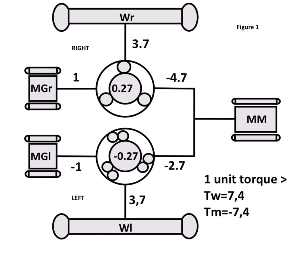
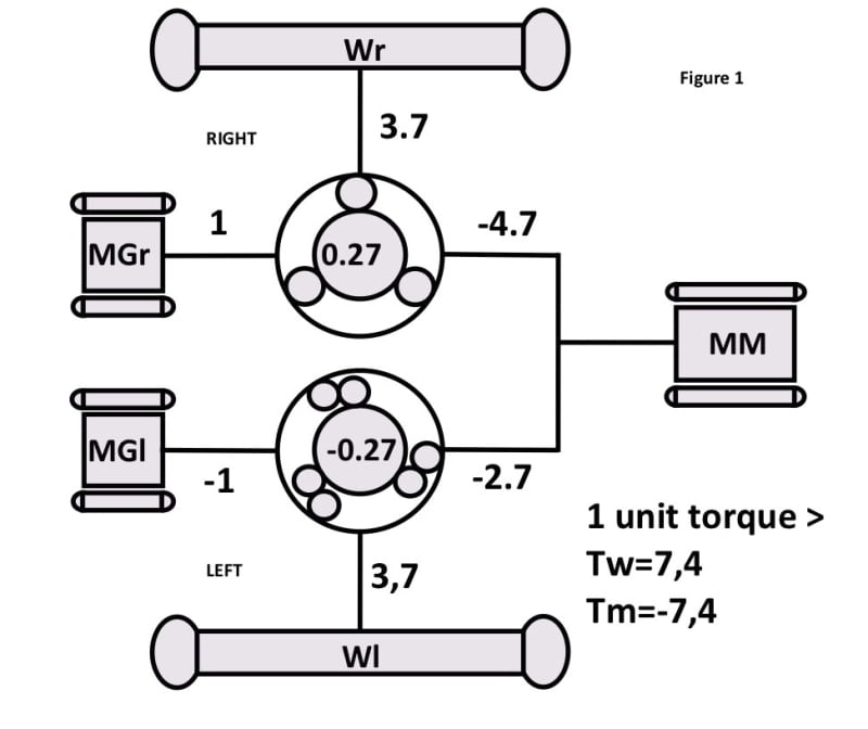
PROPOSED ARRANGEMENT fig 1
The two epicyclic gear sets have one stage, three shafts and two opposite gear ratios. Each set has a “pilot shaft” connected to a motor-generator MG (Permanent Magnets motors). Torques of the MGr at right and of the MGl at left are opposite and in opposition motor–generator on the most useful vehicle speed range. With the tested data, the MGs are in opposition between 88 and 153 km/h. Their power balance is null at 121 km/h.
All shaft torques of the epicyclic gear sets are proportional to the MGr master regulated torque including those of the main motor MM.
The CVTs mainly transfer MM mechanical power. Their electric powers are relatively low and subject to multi-redundancy making the arrangement safer than in an “in-wheel” arrangement.
The main motor MM is anticipated to be a synchronous reluctance type (economic, without rare earth, no rotor winding, air-cooled…). The MGs can help the MM to reach its nominal speed.
(All the gear-reducers for adapting the electric machines to their shaft speed are not represented for clarity).
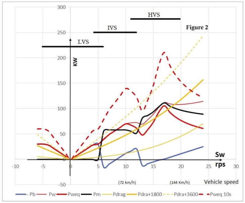
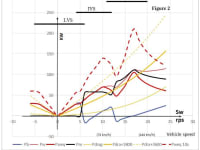
VEHICLE PERFORMANCES fig 2
Three modes:
- The Low Vehicle Speed (LVS): The MM-shaft is electrically or mechanically blocked and the two MGs work as motors.
- The Intermediate Vehicle Speed (IVS): The MM rotates at its half nominal speed.
- The High Vehicle Speed (HVS): The MM rotates at its nominal speed.
On the figure the yellow curves are the requested power for: drag force only, drag force +1800N continuous (long slope), drag force +3600N for 10 s (brief acceleration).
The red curves are the available power when the wheel torques are equal (thick curve), not continuously equal (thin curve), equal less than 10 s (dash line). The black curve is the main motor MM supplied power and the blue curve is the MGs power balance.
Note that for hybrid vehicle, MM can be replaced by an ICE which has a high efficiency on a narrow speed range (usual case).
EXPECTED BENEFITS:
On the efficiency: improvements should be better than for a classic gearbox (up to 12%). That also impacts the battery weight and the autonomy of the vehicle.
On the cost: the high constant speed synRM motor, its electronic and its air-cooling are simple while regulation is only concentrated on the low power MGr and MGl motors .
On the use: we get two true wheel-drives with vectoring and grip control capability, MM is without inertia effect (constant speed).
Like this entry?
-
About the Entrant
- Name:Denis Buffet
- Type of entry:individual
- Software used for this entry:Excel
- Patent status:patented