


ECE directly converts heat into electricity with high thermal efficiency.
Different from traditional direct energy with low efficiency, ECE forces thermal electrons cycling through a Carnot cycle with high efficiency.
By using electronic resonant tank, switches and thermionic tube (with thousands of cells array), the ECE receives heat from the inner wall of the tube and exhaust heat into the outer wall to the cold reservoir, thermal electrons are driven by the resonant tank through a Carnot cycle and generate A.C electricity.
ECE is light and silent, it can be built into various sizes and used in many power generation applications.
ECE is an external combustion thermal engine with no moving parts.
Through thermal cycles of free-electrons in metal or semiconductor, ECE converts thermal energy directly into electricity in high efficiency.
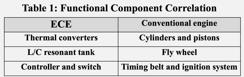
An ECE consists of three key components: (1) thermal converter, (2) L/C resonant tank, and (3) controller and switch.
Table 1 displays correlations in functional components between an ECE and a conventional (piston) engine.
Efficiency of direct thermal energy conversion
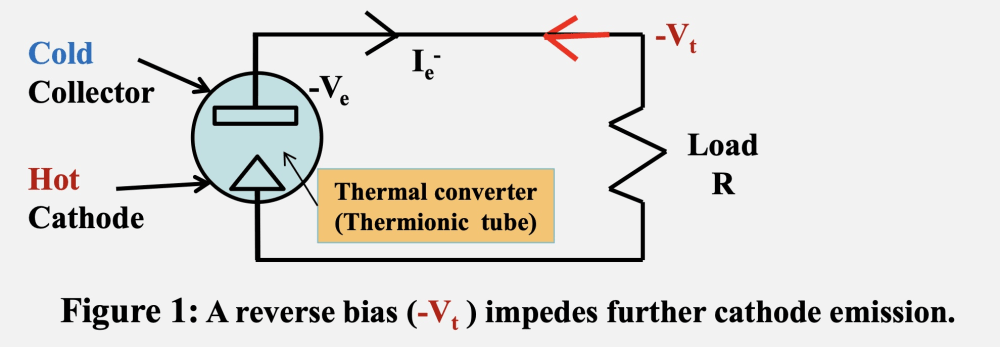
Conventional thermal energy conversion yields low conversion efficiency (approximately 5% to 10%) mainly due to the occurrence of reverse bias.
Take thermionic tube, a typical thermal converter, as an example, current (Ie-) flows across the load R (Figure 1) and results in a terminal voltage (-Vt) in the direction opposite to the cathode emission voltage (-Ve), i.e., reverse bias. (Figure 1)
This reverse bias impedes circulation of the working medium (shuts off the converter) and therefore suppresses further generation of new current, leading to low conversion efficiency.
ECE Innovation
ECE is invented with the aim at addressing the low efficiency issue resulted from direct current (DC) operation in conventional thermal energy conversion.
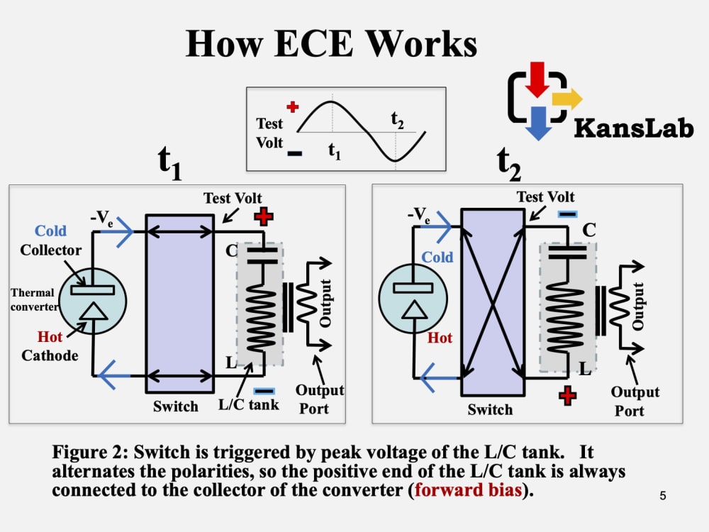
In an ECE, the converter employs forward bias to accelerate the space charge (electrons) in order to maximize current circulation to achieve higher conversion efficiency.
An L/C energy storage tank and a switch provide needed forward bias to the converter when (1) the switch connects proper polarities with the L/C tank and with the converter respectively and (2) the switch operation synchronizes to the resonant frequency of the L/C tank (Figure 2).
ECE – Carnot Cycle
Forward bias turns on the converter, reverse bias shuts off the device.
Massive electrons are accelerated by the forward bias across the space from hot cathode to cold collector – Adiabatic Process 1 in Carnot cycle T-S chart.
Hot electrons are cooled down in the collector – Isothermal Process 2.
Cold electrons are then being accelerated from the collector (via. L/C tank) to hot cathode – Adiabatic Process 3.
Finally electrons in cathode be heated up –Isothermal Process 4. These four processes complete a Carnot cycle.
Like this entry?
-
About the Entrant
- Name:Kan Cheng
- Type of entry:individual
- Software used for this entry:None
- Patent status:none