


This switch (called the EMS) is the heart of a system designed to reduce home residential electrical consumption by at least half, and, with the ability to be tuned for each individual installation, up to 7/8ths of the current electrical usage by playing a trick on electricity.
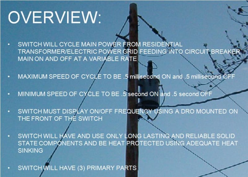
The switch is installed between the incoming electrical grid power supply (in this case the 220V/200A common service input power line) and the main feed-circuit breaker, which can be any brand.
When properly tuned, the switch maximizes the relationship between the upward positive or negative climb of the input power sine wave and the rise and fall times of the electronic components of the circuit it is attached to by introducing a frequency to the input power.
In plain terms, the power is cycled faster than the components in the appliances plugged into the residential circuit the EMS is in line with can react - to the power being turned off, before power is turned on again.
For example, at "x" frequency, the EMS cycles power on & off every half millisecond. In the same half hour, of appliance use, its input power was turned off every half millisecond and on every half millisecond. The appliance didn't notice this because the rise and fall times of its electronic (capacitive and inductive)components are slower than the half milisecond power cycling frequency. Therefore they maintained state. Yet the power was actually off, half the time. So cumulatively, the appliance ran for a half hour, with fifteen minutes worth of electricity.
The EMS is automatic and works whenever a load is applied, instantly providing the electrical conservation it was designed for.
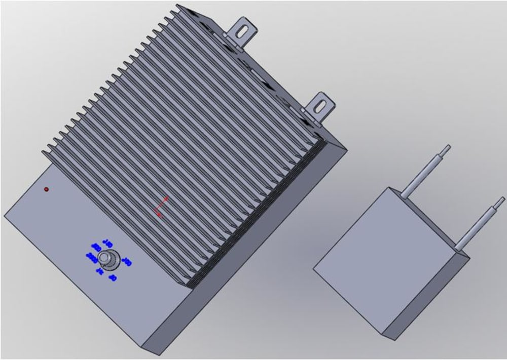
The EMS is a part of a packaged system consisting of a stage 1 safety switch that allows emergency generator power without feeding power to the grid, the EMS as stage 2 to provide the power cycling advantage, and stage 3, a power scrubber circuit designed to eliminate "dirty" power characterisitcs of both the input power conditioning and transient spikes caused by cycling inductive loads.
The entire system is encased in a box similar to a circuit breaker and all the technology is commercially available and robust. It can be installed on-wall of the residential interior or exterior and can be applied to any 220V/200A service...now.
The shear amount of electric inefficiency in our homes and businesses begs this technology and mandates similar technology due to the potential for savings and growth it represents. The unit cost of a single system installation not only saves the homeowner half on their electric bill at minimum but doubles the service that same amount of electricity can offer, over the same time.
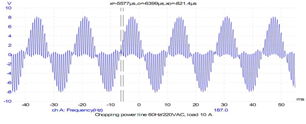
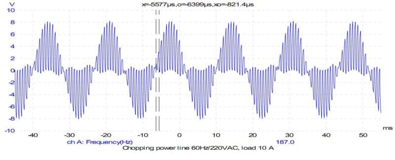
The prototype switch was spec'd, built and tested under it's maximum operating conditions for a month. It performed flawlessly and proved the concept works. Please see the wave form illustrations. Winning this contest provides the funds for the beta site testing representing the final development phase prior to mass distribution.
Thankyou for your considerations.
Tom
Like this entry?
-
About the Entrant
- Name:Tom Bevolo
- Type of entry:individual
- Hardware used for this entry:EMS PrototypeSoftware used for this entry:Microsoft Office Suite, SolidWorks
- Patent status:none