


Abstract
Porcupine Quill ceramic heat exchanger promotes both - free air circulation and maximization of caloric transfer capabilities. The ceramic has half the weight of copper and three-quarters the weight of aluminum and is resistant to most corrosive or abrasive effluents with caloric conductance of .375, relative to that of copper. For various liquids this type of exchanger offers greater heat conductance per inch of construction than other types of exchangers. The quills originate at the center of the tube, and travel through the wall of the tube to the air. As the construction is molded in place, there are no seams to weaken the structural integrity of the tube. The tubes may be molded in linear, sinusoidal or spiral constructions without compromise. Each tube quill is spaced at .238” linearly and 90 degrees radially from the proceeding quill. In the case of the circular exchanger the quill at polar 90 degrees is almost always eliminated.
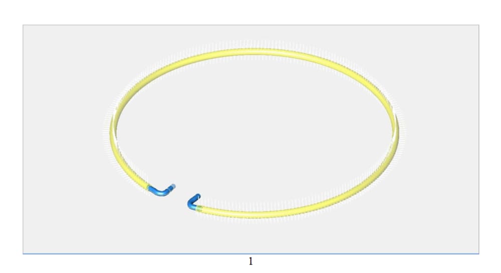
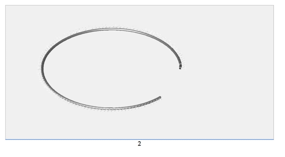
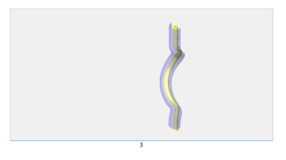
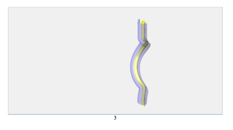
In the applications described the concept is used in case {A} 1 & 2 to effuse caloric energy and in case {B} 3 to infuse caloric energy.
The first picture is a circular heat exchanger tube, shown are the vertical quill and left side (240) quill. Note the thick surface area to promote transfer of caloric energy to the tube walls. The quills cause turbulent flow, of the fluid which also promotes full fluid exposure to the quills and, tube to promote caloric energy transfer from the fluid to the component. Statistics; The surface area of the above is 134.59214 in. sq. The total volume is 155.95197 cu. in. Thermal conductance 20188.8225 Btu/hr.
The second picture is another construction of an effuse tube where 68 degree offset quills providing room to clear a grooved receptacle formed to support the half of the tube surface of the exchanger.
The third picture is an infuser quill tube, constructed in a sinusoidal manner. In this version a tube within a tube construction is utilized to confine caloric energy enriched fumes from combustion, which then impart that caloric energy to the fluid, which, in its turn, is traveling within the inner tube. The long quills promote turbulent action of fumes, guaranteeing exposure of the volume to surface interface at least, twice during the transition.The illustration is the tube-within-a-tube construction depicting the inner tube-within-a-transparent outer tube. One-half of the outer tube is hidden.
Conclusion
The ceramic heat exchanger offers a possible difference of application to metal while performing effective conduction of caloric energy. Modeling shows that the effective area of the device affords a high ratio of surface area to fluid area exhibiting greater performance. With the protection from corrosion and abrasion the ceramic heat exchanger offers a viable choice. The cost of construction also offers advantages especially in high production.
Like this entry?
-
About the Entrant
- Name:Wayne Pickette
- Type of entry:individual
- Hardware used for this entry:Gateway LaptopSoftware used for this entry:ViCad 7
- Patent status:pending