
This design consists of the following elements: 1. water holding system 2. a turbine 3. water pumping system.
Water holding system consists of two pits and an interconnecting tub of predetermined dimensions.
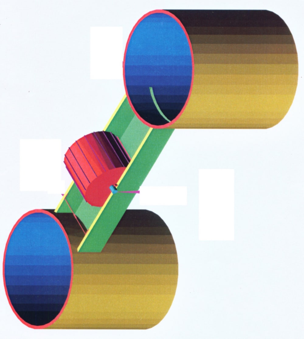
Turbine consists of a closed cylinder with shaft at the center of its diameter and blades weld on the circumferential surface with predetermined dimensions and angle. Turbine diameter should be minimum 2 meters. The length of the turbine shall be the width of th tub. Turbine is fixed to the tub at its center. The turbine blades will be very close to the bottom of the tub. At the bottom of the tub, where the turbine is fixed, an arc shaped plate is fixed so that the turbine blades will be moving within the arc shaped plate. After complete manufacture, the turbine should have a specific gravity of 0.25 or less.
Now water is fed to the system. Water level will be 60% of the depth of the tub. Pumping system will be installed with the following conditions. Suction tube will b 0.5 meters below the water level in the suction pit and delivery tube will be 0.5 meters above the water level in the second pit.
We start pumping the water from suction pit and deliver in the second pit. There will be slight rise in water level on the delivery side and turbine starts rotating and the water will be reaching back to the suction pit. This rotation should be maximized by increasing the quantum of water pumped.
SCENARIO 1
785 liters/second of water is pumped. Assuming the vertical height of the blade is 0.15 meters, the turbine RPM would be 50. Velocity of water at blade point will be 5 meters/second.
Energy given by water to the turbine would be half the product of mass and velocity squared. 0.5 X 785 X 5 X 5 = 9.8 KW.
The turbine shaft must record a minimum f 19.6 KW. This due to mechanical advantage. Input to the motor-pump would be, MGH. With an assumed overall efficiency of 50%, the input would be 15.4 KW.
SCENARIO 2
Increase the quantum of water pumped to 1570 liters/second. Turbine RPM would be 100. Velocity = 10.47 meters/second.
Water power given to the turbine, 0.5 X 1570 X 10.47 X 10.47 = 86 KW. Turbine shaft records 172 KW output. Input given to the motor-pump with an efficiency of 50% would be = 31 KW.
SCENARIO 3
Increase the water pumping to 3140 liters/second. Turbine RPM would be 200. Velocity 20.94 Meters/second. Water power given to the turbine = 0.5 X 3140 20.94 X 20.94 =688.4 KW. The shaft must record 1376 KW. Input to the motor-pump with 50% efficiency would be = 61.6 KW.
The more the diameter of the turbine, the more the mechanical advantage. According to this system, we can design and generate power near the point of consumption. We can generate required quantum of power. This method of power generation avoids environmental pollution.
Like this entry?
-
About the Entrant
- Name:Chalasani Veerabhadra Rao
- Type of entry:individual
- Hardware used for this entry:mild steel and cement concreteSoftware used for this entry:nil
- Patent status:pending