


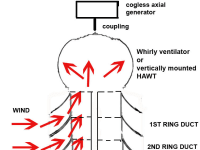

The original idea was to make a small axial generator to fit on top of existing “Whirly Bird” axial roof ventilators. However, the effective swept area of a whirly ventilator is small and with a wind speed of 4m/s (annual Western Cape average) it could not be expected to produce more than 20 watts. Not a cost-effective proposition, but there are a lot of guys re-cycling various motors, magnets etc. who may be happy trickle-charging batteries for little or no cost using this idea.
.
Roof ventilators have relatively efficient rotors, streamlined, lightweight and with long lasting bearings. There must be some way of utilizing them for power generation. Tests show that the ventilators turn faster when the airflow is vertical from below, rather than horizontal.
Extracting more power from this turbine could be achieved by increasing either the rotor size or the airflow. Increasing the rotor size to achieve this would not be practical. Using the roof surface as a scoop would only work if it faced the prevailing wind.
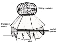
A curved horizontal duct could change the wind direction from horizontal to vertical, directing the airflow up the centre of the ventilator. To make the system omni-directional, a ring of ducts would be required. This would avoid the use of a rotating baffle. Some entraining of air below the assembly would probably take place.
The design of the ring duct would be a modified mixed-flow pump impeller with the wind entering horizontally at the edge and exiting vertically near the centre.
A crude single ring of ducts made of Correx board was used to test the idea. It was tested indoors using fans with promising results even though it looked like a “Dalek” from” Dr Who” TV series.
It should be possible to stack a number of these rings on top of each other; each ring would increase the volume of air entering the turbine from below. Using this method, the speed of the turbine could be raised without an increase either in wind speed or in the size of the turbine. The dimensions of the model were determined by the material at hand. The model diameter was 750mm - larger diameters would increase the swept area. Some simulation and wind loading calculations need to be done before a prototype can be built. It will be mast-mounted and probably made of spun aluminum sheet.
The generator would need to be a cog-less axial type using neodymium magnets. There are many designs of these available on the internet. These modifications could be made to existing installations if weather-proofing was not an issue.
Some problems associated with existing turbines could be avoided
1) Large rotors, rotating electrical connections, self-starting and high noise levels.
2) The ventilator rotors are simple, rugged and readily available at a reasonable cost.
3) Fabrication of the ducts would simple and cheap.
4) Erection would be simple due to the light weight and compactness of the unit.
Like this entry?
-
About the Entrant
- Name:Michael Ashford
- Type of entry:individual
- Profession:
- Number of times previously entering contest:never
- Michael's favorite design and analysis tools:Photoshop & Illustrator
- For managing CAD data Michael's company uses:None
- Michael's hobbies and activities:being inquisitive , bee keeping, brewing, wine tas
- Michael belongs to these online communities:some aquaponics and permaculture sites
- Michael is inspired by:the world around me
- Hardware used for this entry:pc winxpSoftware used for this entry:msword, adobe photoshop
- Patent status:none