VORTEX ENERGY REPRODUCTIVE SYSTEM
ABSTRACT
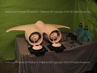
Implosive energy apparatus FIG. 1 utilizing multi disciplinary concepts comprising super low pressure ducted fan vortex turbine engine 10 attached to canard nacelles airfoil structures 17 comprising asymmetric shaped ducted sleeve intakes 35, 36 rear outlets 15,16 FIG. 1, 15, 16 and 31 - 42 attached to the engine casing by brackets and flow stabilizing vanes 17 and conical portions FIG. 1, 5 - 33 attached to the frontal area ducted sleeves comprising fan shrouds 34 intakes 33 35 36 debris guards 34 and comprising an air vortex energy reproductive system.
BACKGROUND
Universal interest forecast the development of nonpolluting alternative energy sources particularly renewable e.g. wind energy and the reduction of dependency upon fossil fuels thereby reducing particulate contaminates released into the environment.
This invention proposes to eliminate long power transmission lines by the development of devices that concentrate wind energy via increasing vortically manipulated wind velocities through vortex action, thereby enabling wind forces comprising lower ambient velocities and energy densities to be utilized for electricity generating systems. Thereby increasing the economics of scavenging wind energy in areas with less concentrated winds currently inaccessible to conventional propeller driven turbines.
This approach utilizes a diffuser duct, the ducting helps to create a lower pressure, thus drawing a faster air stream through the smaller diameter inlet. The aim of this invention is to improve energy conversion of air driven turbines by increasing rotary velocity through multi cyclonic action but manly to design an energy reproductive system to do useful work on both the wind up and the wind down cycles of energy.
TECHNICAL FIELD
Innovation is concerned with electricity generating via implosive thrust turbine engine affixed as auxiliary power generating station or as a propulsion system. Controlling fluid flow patterns along inner and outer ducting enhances performance in asymmetrical shaped turning vane surfaces. For this purpose a free rotor airfoil component redistributes the inner fluid stream passing through the conical inlet into the outer stream of the inner ducting via centrifugal rotation and rerouting the fluidic stream axially via internalized airfoil vanes thereby converting energy into a super negative low pressure vortex sink and fluidic stream allowing this energy to be converted mechanically into electricity and into a propulsive thrust.
The invention is applicable to combined augmentation technology turbines (CATT) also comprising aircraft, automotive fuel economy, wind and underwater applications.
Alternative embodiments envisioned herein disclosed but not by way of limitations include turbo charged windmill designs, under water dive for scuba scooters, diver-towing apparatuses, pilot-able aircraft including radio controlled (RC) toy electric and implosively electric powered ducted fan jets (IEDF) and as axially power for charging batteries for electric propulsion e.g. transportation comprising electric vehicles (EV) or (IEV) implo-electric-vehicles when the invention is built directly into the EV.
Articles of this invention are capable of being fabricated using indigenous materials, examples include plastics, fiberglass, CNC milling molds vacuum chambers other methods of manufacture which are well suited to the fabrication of aircraft, boats and automotive.
Like this entry?
-
About the Entrant
- Name:Robert Patterson
- Type of entry:individual
- Software used for this entry:Windows PC
- Patent status:none


