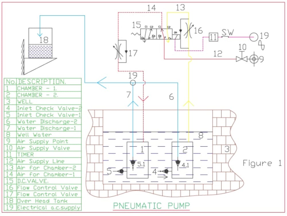

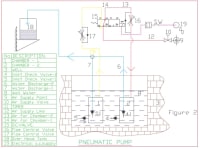
The pneumatic pump proposed below comprises 1) Air Controller, 2) The Pumps, & 3) Hose Connections.
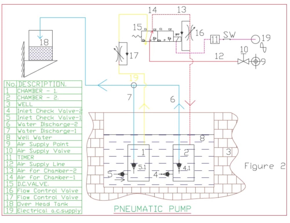
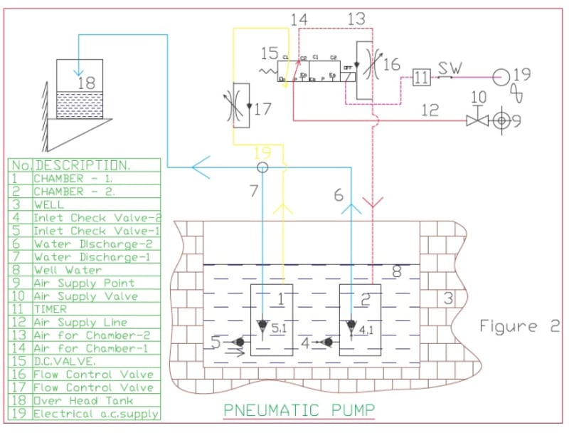
The pumps (Part no.1&2) are simply cylindrical hollow containers. They do not have conventional rotating or reciprocating components like an impeller, piston, bearing etc. They are connected to check valves (foot valves) 4,4.1, 5, 5.1. as shown in the figure and submerged in the well 3. Air source 9 is connected to a 5 Port, 2 Position, Solenoid by spring return Directional Control valve 15 through an electrically operated isolation valve 10. The solenoid of the DC valve is connected to electrical power supply 19 through a switch, timer 11. The water from well 3 is pumped to an over head tank 18 as follows. Initially when the pumps are not connected to air line 12, water gets filled in Chambers (Pumps) 1&2 due to hydrostatic pressure acting over them by opening foot valves 4,5. Now if air connection and electrical power is given to them, (as shown in figure1), solenoid of DC Valve 15 gets energized. Air flows in the line marked in Red color as shown via. 9 – 10- 12- ( P to C1 Ports of DC Valve) – 14, flow control valve 17, goes to chamber 1. and pressurizes water in chamber. Thus the water in the chamber gets pumped by opening foot valve 5.1, thro’ line 7, T connector 19 and finally discharges to Tank 18. Simultaneously chamber 2 gets filled by opening of valve 4. The trapped air in the chamber2 gets vented thro’ yellow line as shown, finally via. Port C2 to Exhaust port Ea and exhausts to atmosphere. After some time (as pre-set in the timer) the electrical supply to solenoid of DC Valve is cut. The DC Valve port position changes as shown in the figure 2. Now the red line (pumping air) and yellow line (vent line) changes as marked in the figure2. Hence pumping takes place in Chamber 2 and filling takes place in Chmaber1. The cycle of energizing and de- energizing of solenoid of DC Valve 15 is repeated alternately at regular time by the timer. This generates a pneumatic oscillations or pulses alternately and fed to pumps which gives continues flow to over head tank.
The pump can be used for deep water pumping. The pressure required to lift the fluid is given by the equation p = w H. The pump can be used for mixing two different chemicals/fluids at different proportions. The circuit can be modified /extended for mixing many different chemicals at different ratios at different instances of time.
As the pump has less moving components maintenance is easy, easy to install, easy portability, cheap and can be used for pumping hot fluid, pumping dirty fluid etc. In case where compressed air is not compatible for the fluid to be pumped alternate gasses like N2 can be used. The flow control valves 16 &17 are synchronized with respect to the timer frequency by manual adjustment.
Like this entry?
-
About the Entrant
- Name:Ravi Paramanandam
- Type of entry:individual
- Software used for this entry:Auto CADD
- Patent status:none