


This is an innovative design for a sensor to measure the spin of rockets. The spin sensors that are available today use a gyroscope or an accelerometer. These instruments are expensive and require a lot of electronic equipment and are easily damaged. This sensor is compact and can be used in various aerospace vehicles like sounding rockets, missiles, etc. This sensor has ball bearings configured in a particular way so as to create a non-rotating reference inside the sensor. It is with respect to this non-rotating reference that we measure the spin of the rocket. The configuration of the ball bearings is unique and innovative and creates a non-rotating object inside the rocket. After we succeed in making a non-rotating reference, we place a transmitter on this non-rotating reference. We also place a receptor on the inside of the rocket body. The receptor will receive a signal only when the transmitter and receptor come in line. This happens only once in a rotation. So, if we measure the time between any two successive signals received, then we can measure the spin of the rocket. The ball bearing used in this sensor can be made of ceramics to reduce weight. This sensor is independent of the climatic conditions. The electronic circuit required for this sensor is simple and less expensive. It is a low power consuming sensor.
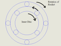
Let us assume that the rocket rotates in the clockwise direction, as shown in the figures.
In the ball bearing configuration on the top, the rotation is transmitted to the inner disc.
Eventually, the inner disc acquires a clockwise sense of rotation.
In the ball bearing configuration at the bottom, the sense of rotation transmitted to the inner disc is anti-clockwise. The inner disc on the top and the inner disc on the bottom are connected together by a shaft.
Hence the clockwise sense of rotation on the top and the anti-clockwise sense of rotation on the bottom of the connecting rod cancel each other and thus the connecting shaft remains stationary and does not rotate.
There is a transmitter placed on the non-rotating shaft and a receptor on the rotating outer shell of the sensor.
If the time between two signals received by the receptor is measured, then the rpm of the rocket can be determined.
W = 2?/T
Where,
W -> angular speed (radian/second)
T -> time period (time between two signals received)
If we place more than one receptor, then we can determine whether the spin is clockwise or anticlockwise.
Now, the use of ball bearings leads to many uncertainties. Due to the friction of the ball bearings, the torque that is transmitted at the top and the bottom set of ball bearings may not be the same. This will lead to the inner cylinder not remaining non-rotatory. It will lead the inner cylinder rotating. To overcome this problem, we will have to calibrate the sensor on a spin table before actually putting it to use.
Like this entry?
-
About the Entrant
- Name:Vibin Varghese
- Type of entry:individual
- Software used for this entry:Solid Works
- Patent status:none