


Emerging electric vehicles require high starting torque smooth running high power tracking motors. Developing such motors is a technological challenge.
Currently, hybrid and electric vehicle use motors with rare-earth permanent magnets in the rotor. This eliminates providing current to the rotor which eliminates power loss, and decreases maintenance. Stator fields are switched by power semiconductors driven by processor controllers. This permits performance to be tailored by sophisticated algorithms. Rare-earth magnets such as neodymium-ferrite-boron are used since they can produce fields of about 1.5 Tessa’s matching that of electromagnets. The problem with rare-earth magnets is that they cause the nascent electric car industry to strain world resources.
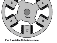
Switched variable reluctance motors (SVRMs) also operate without electrical connection to the rotor or with permanent magnets. Fig. 1 shows a diagram of a SVRM. Three electromagnetic pole pairs are shown. To rotate the rotor, the proper pole pairs are energized one at a time.
By feeding trains of properly timed pulses to the poles, the SVRM can be made to run essentially as a synchronous motor. Its biggest problem,as a traction motor,is “torque ripple” caused by sudden surges of flux through the rotor poles as they pass the electromagnetic poles.
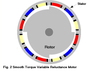
My invention is a modified switched variable reluctance motor (SVRM) driven by a processor. The SVRM is capable of high field strengths in both the rotor and stator without any permanent magnets (Fig. 2). The rotor, stator, and electromagnet cores are constructed of a high permeable material with a saturation knee of about 1.5T such as amorphous steal commonly used in transformers.
In the example shown (Fig. 2),this motor is divided into symmetrical quadrants. Each quadrant contains three electromagnets. Each is color coded in the diagram as yellow, blue or red to indicate that it belongs to a group that is simultaneously energized.
The rotor is a right cylinder with a radius that varies gradually in each quadrant from a minimum to a maximum and then in a step back to minimum. The electromagnets are positioned on the stator such that a varying air gap is formed as the rotor turns.
To initiate clockwise rotation, magnets in the same group but 180-degrees apart, are reversed polarized. An attractive force normal to the rotor is formed, Fn=2AB-squared ?(sub)0, where A is the area under the energized poles. Except for fringing this is a fairly constant force even as the size of the gap changes; it creates vectorily a force tangent to the rotor that turns it. The energy under these gaps, U(sub)g=wAB-squared/2?(sub)0 ,where w is gap width, is continuously converted to work.
As soon as a step rotates to a pole, the pole de-energizes and energizes after it clears the step. To provide smooth torque only two groups are energized at any time. Reversing the sequence and making all magnets like poles will make it run counterclockwise. By energizing one magnet and taking power from all the others, this motor can be made to brake regeneratively.
Like this entry?
-
About the Entrant
- Name:Fred Etcheverry
- Type of entry:individual
- Software used for this entry:DraftSight, TNT
- Patent status:none