


Historically, lobe pumps have not had wide spread industrial use because of the problems of pulsating flow, large size due to low rotor speed and low NPSH. A company in California is testing a new design that will change all that. The new design, called the OCOR Multiple Segment Lobe Pump, supplies continuous flow, high volumetric efficiency (83% - 92%), variable speed, high NPSH, high flow rate and is fully reversible.
As the name implies, the pump mechanism is made up of a collection of individual helical lobe pump segments that share a common inlet and discharge. Each pump segment is isolated from the adjacent pump segment by a stationary flat plate that is held in place by the containment housing.
Prior to the OCOR Multiple Segment Pump, a continuous flow three lobe pump was never a practical pump design because continuous, non-pulsating flow requires that the helical wrap angle of the individual lobes must be equal to 360o divided by the number of lobes or, in this case,120o. When the individual pumping chamber, which is the space between adjacent lobes, is filled by the inlet flow, the chamber must be isolated from the adjacent chambers as it rotates toward the discharge region. After 120o of rotation, the trapped material (semi-solid or liquid) flows into the discharge region. Total rotor angular movement of the isolated volume is therefore 240o.
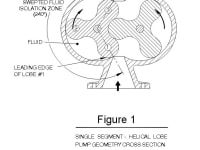
Figure 1, which is a generic cross section of a single segment, dual rotor, helical lobe machine, should give a better understand of the limitation of the design. The shaded region in the figure is labeled ‘SWEPTED FLUID ISOLATION ZONE’ and represents one full pumping chamber. The lobes of the rotor on the left side of the figure are numbered 1 thru 3 to aid in the understanding of the flow sequence. The leading surface of lobe #1 is at the top of the rotor and extends clockwise 120o, or on other words, to the bottom of the lobe #2. The helical mass of liquid occupies the region between the two lobes 1,2 and 2,3.
The figure clearly indicates, the required 240o isolation zone imposes an opening limitation on the inlet and discharge regions of the pump, rendering the design virtually unusable for most applications.
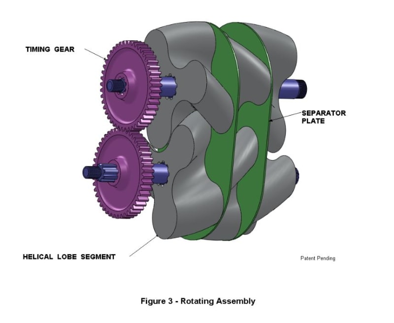
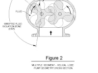
The new design, shown in Figure 2, illustrates that by separating the rotor into three equal, sequentially aligned pump segments on each shaft, allows ample space for the inlet and discharge openings because the swept isolation region is now only 160o. A three dimensional view of the parallel shaft rotating assembly is shown in Figure 3.
For the three rotor configuration shown, two separator plates are required along with the housing end surfaces perpendicular to rotation to make up the ‘total flow’ pump chamber. Additional separated rotor pairs can be added to increase the inlet NPSH.
The applications for this design are extremely diverse and as such, could have a significant impact on the entire pump industry.
Contact: Brian O’Connor (619) 328-1310 or email: ocor@cox.net
-
Awards
-
 2013 Top 100 Entries
Like this entry?
-
About the Entrant
- Name:Brian Oconnor
- Type of entry:individual
- Software used for this entry:AutoCad & SolidWorks
- Patent status:pending