


A practical electric vehicle direct drive traction motor must be capable of accelerating into traffic from rest, be able to run at highway speeds, be capable of regenerative breaking and running in reverse. Such a motor must be brushless since using brush slip rings to feed current to a rotor is inefficient and require high maintenance. Brushless synchronous machines have been constructed using an auxiliary armature on the rotor shaft to generate current for a wound rotor.
Most current hybrid electric vehicles use a traction motor with niobium and other rare-earth permanent magnets imbedded in there rotors. The price of niobium and other rare-earths is escalating as demand increases.
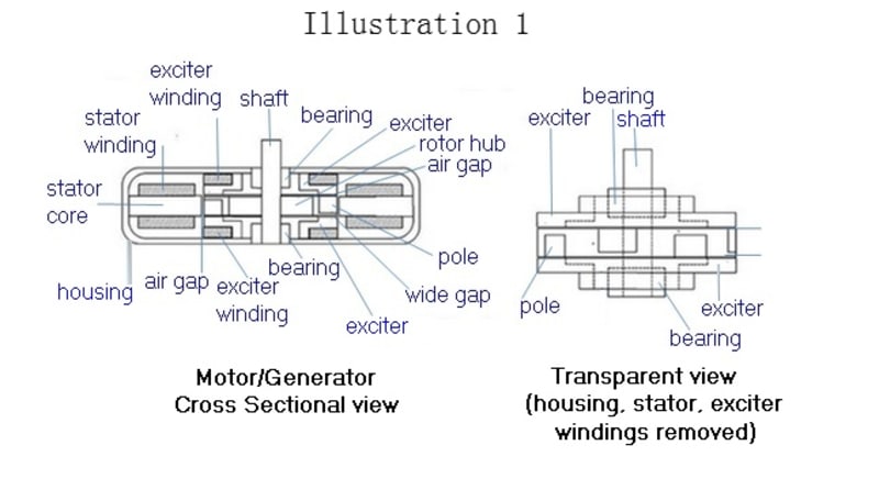
Illustration 1 shows a complete motor/generator incorporating prior art with novel features—flux exciters and soft magnetic rotor poles.
My invention utilizes only electric magnets. The stator is wound as prior art, but the rotor poles are fed magnetic flux from an external electromagnetic exciter through air gaps at both ends of the rotor.
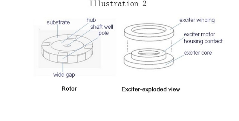
Illustration 2 shows the rotor with soft magnet poles, such as, those made from silicon steel or other high permeable material. These poles receive their magnetic field from stationary exciters across rotor-exciter air gaps. Operating on the saturation knee, enable these poles to exceed 1.5 teslas—a field strength that can match the best rare-earth magnets
The rotor substrate is a non-magnetic material. The wide gaps provide high reluctance to prevent flux shorts.
Next an exciter core and its winding are shown. The housing contact makes physical contact to the motor housing. Although the exciters require power, they enable a better range of torque-speed and power factor control .The exciters occupy unused space around bearings and often protruding hubs.
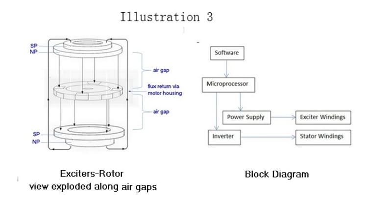
Illustration 3 shows a view of the exciter cores and the rotor. The arrows show the conventional direction of flux flow from north poles NP to south poles SP. Flux flows to the top rotor poles making them NPs and from the bottoms rotor poles making them SPs. These rotor poles are pulled around by the stator’s rotating field. Thus flux flows from the top poles to the stator core (not shown here) and back to the bottom poles. The motor housing is the flux return.
Next a block diagram shows a microprocessor controlling motor speed and direction by the power inverter. This is prior art. The control of a variable power supply to control flux of a non-wound rotor is novel.
My invention is relatively easy to manufacture from inexpensive materials. The rotor poles are blocks that can be pressed into slots and bonded. These poles can also be wedge shape to present a greater area to the exciters and reduce the reluctance of the rotor exciter air gaps and the reluctance of the poles by keeping the flux below the saturation knee until it reaches the curved surface of the poles. Since the rotor can be produced by milling, it is easy to dynamically balance.
Like this entry?
-
About the Entrant
- Name:Fred Etcheverry
- Type of entry:individual
- Software used for this entry:DraftSight/TNT
- Patent status:pending