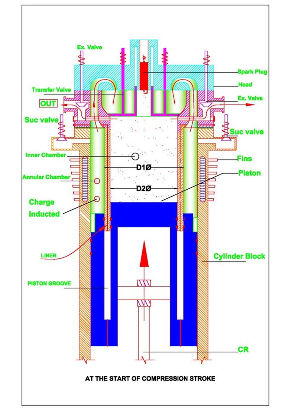
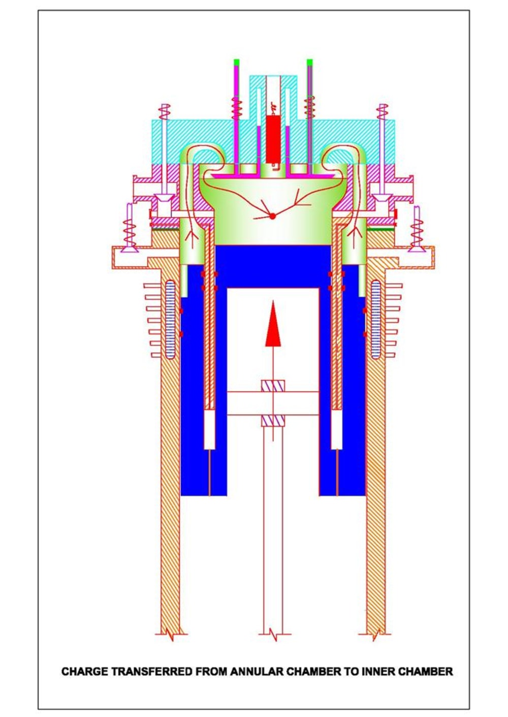
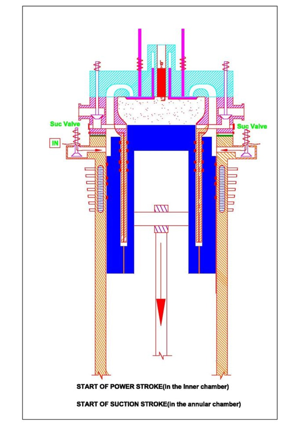


This proposal relates to a Hybrid Split Type Internal Combustion Engine. The hybrid construction has resemblance to a four stroke engine having valve arrangement but produces Power for each rotation like a two stroke engine. A special valve prevents carryover of fresh charge with exhaust which is an inherent drawback of conventional two stroke engines. This is an alternate arrangement to the proposal published in this contest in the year 2010 under the title “Valved two stoke engine with extended expansion”. The model which was previously submitted is a Stepped Piston arrangement whereas the present proposal is Grooved Piston arrangement. Referring to the figures, a circular groove is machined from the top of the piston extending to a depth slightly greater than the stroke length of the piston. A cylindrical liner of OD = D1 & ID = D2 extends downward from the cylinder head. The grooved piston simultaneously reciprocates both in the cylinder block and the liner. Thus engine construction is split to form two regions Viz. annular chamber at outside the liner and an inner chamber. The liner acts as barrier in between them. Suction and Compression cycle takes place in the annular chamber while Power and Exhaust cycle takes place in the inner chamber. The inner volume is greater than annular volume causing expansion ratio greater than compression ratio. Hence products of combustion expand to a larger extent following Atkinson Cycle. Hence more thermal energy is converted into work. This saves fuel, reduces emission temperature and exhaust noise level. The working is given below. When piston moves down from top to bottom, Suction Valve opens and charge is inducted in the annular chamber. When piston reverses up: Suction valve closes, Transfer Valve moves down and Exhaust Valve opens venting out burnt gas of previous cycle at approximately 60% of upward stroke. Simultaneously the inducted charge in the annular chamber is compressed, moves and waits in the inner chamber above the Transfer Valve. Thus mixing of fresh charge with the outgoing exhaust as prevailing in conventional two stroke engine is prevented and hydrocarbon emission is controlled. After this exhaust cycle, the Exhaust Valve closes & Transfer Valve lifts up. The fresh charge which was waiting in the traffic above the Transfer Valve is now diverted to inner chamber. Further movement of piston compresses the transferred charge to the clearance volume and fired which is the Power stroke (simultaneously suction stroke in annular chamber) and cycle continues further. However as charge has to fill in a constrained space of annular arrangement, volumetric efficiency will be very poor (esp. at high RPM). Also the complex valve mechanism is an added disadvantage. Latter the drawbacks in the precursor model (Patent obtained) were eliminated by suitable modification to augment high volumetric efficiency (without involving additional component like turbo/supercharger). The revised model (applied for Patent) will have only two conventional type poppet valves; the engine construction is much simplified to have less floor area, less weight/BHP and less cost.
email: paravi59@gmail.com
Like this entry?
-
About the Entrant
- Name:Ravi Paramanandam
- Type of entry:individual
- Software used for this entry:Auto CADD
- Patent status:patented