


RANGE DETECTION CAMERA
The Range Detection Camera (RDC) can measure the distance from each pixel to the point on the object that is in focus at the pixel. Each pixel has both light intensity and range information. There is no stereoscopic effect involved.
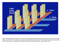
There is a light guiding post at each pixel that functions as a passive LIDAR, see Fig. 1. The passive LIDARs use broad band light instead of light pulses. The camera lens selects the point on the object for each pixel to which the distance is to be measured. At each pixel only light from the object point that is in focus at the pixel adds constructively, see Fig. 2. Light from all other object points cancel at that pixel. This works throughout the depth of field of the lens. The camera functions with broadband partially coherent ambient light.
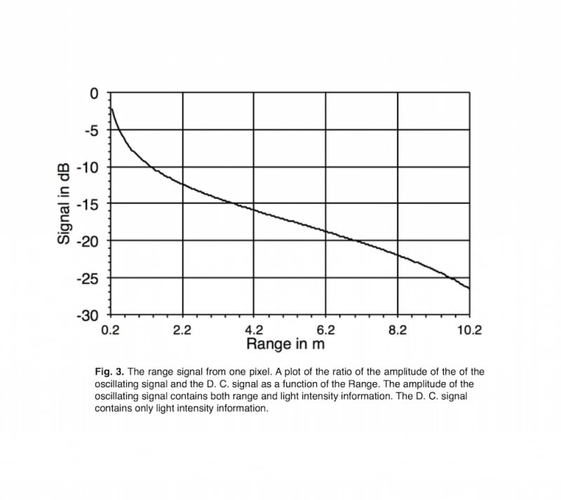
Each LIDAR post produces a D. C. electrical signal that has only light intensity information and an oscillating electrical signal. The amplitude of the oscillating signal has both light intensity and range information. The oscillating signal is noise like, since it is derived by an autoheterodyne mechanism from broadband partially coherent ambient light. An example of the ratio of the amplitude of the oscillating signal and the D. C. signal as a function of range for one pixel is shown in Fig. 3.
There are many applications. It can be used in guiding autonomous vehicles. It can be used to replace the Infra Red scanner in the Wii games and in similar applications. It can be used for facial recognition. Another application is part of a crude Teleportation System. This camera can be used to obtain all the dimensions of an object. This data can be transmitted to a remotely located 3D printer that would reconstruct the object.
This ranging system uses broad band ambient light. The various light frequency components are only coherent in spherical light packets one coherence length thick. Each frequency component in the light packet acquires a phase proportional to the distance the light packet traveled. Each frequency component produces a pattern in the light guide post. The light patterns shift in response to the phase of the incoming light. The photocurrent at each point in a light guiding post is proportional to the light intensity at this point. The contacts sum the total photocurrent in each post. The light intensity is proportional to the product of the light electric and magnetic fields. Both the electric and magnetic fields of the broad band light have components oscillating at many different frequencies. The product of two waves oscillating at different frequencies is equal to the sum of a wave oscillating at the difference frequency and a wave oscillating at the sum frequency. The sum frequency waves are in the UV and are not detected. The difference frequencies range from zero to light frequencies. Though the photo current detecting electronics can detect at most radio frequencies.
Like this entry?
-
About the Entrant
- Name:Philipp Kornreich
- Type of entry:individual
- Software used for this entry:Future Basic 4
- Patent status:none