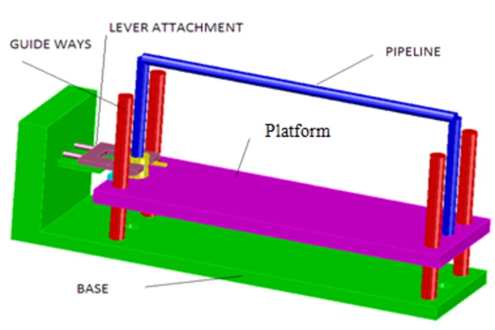


Water is one of the important and life supporting resources and most of the drinking water supplied to homes is not done at proper timings in most of the cities, so most of the people are not able to get their share of water. A device which can be used to fill the water in a container and automatically stop it when the container is filled without human assistance is a permanent solution for both the above mentioned cases. A design of the system was synthesized and using modeling software it was designed. Given in illustration 1. The automatic water flow control shut off system consists of following parts.
FRAME acts as the base for the springs which is placed below the platform. PLATFORM is used to carry the four pots and is displaced with the help of spring. COMPRESSION SPRINGS are placed in the four corner of the frame. It provides the downward movement when the weight is increased by filling the pots with water. WEDGES are important component of the mechanism used to engage in between themselves. And they get disengaged when the four pots are filled. TENSION SPRING is used to shut off the valve once the contacts between the wedges are removed. BUSHES places the springs in its position. FLOW CONTROL VALVE is used to control the flow of water from pipeline. GUIDE WAYS prevents the springs from any deviation and guides the platform to slide along it from top to bottom. PVC PIPE helps to transfer the water from source to pots. LEVER helps to close the valve.
Working
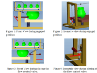
The pots are kept in the platform after engaging the wedges and are left as such. When the water supply is turned on the pots starts to fill, the increase in weight of the pot lowers the bed and it moves downward slowly with the opposing force from the spring. The wedge1 is integrated to a circular rod by a welding and slides on the guide and is held in position by a compression spring. The wedge2 is welded to platform and can be locked with the wedge1 during loading Illustration 2 Figure 1. and Illustration 2 Figure 2. When the platform is lowered the wedge2 also moves downward by compressing the tension spring Illustration 2 figure 3, after a downward displacement of 17 mm the contacts between the wedges is broken. The wedge 1 is made to moves toward the shutoff valve by the compression spring and this in turn closes the stop valve Illustration 2 figure 4 and the water flow. To reload the system the three pots are removed and the wedges are reset to the initial loading position. And then the process is repeated again and again.
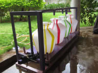
The prototype is given in illustration 3 and the working mechanism is given video https://www.youtube.com/watch?v=r0xbI19AU1A.
Video
Like this entry?
-
About the Entrant
- Name:Renold Elsen
- Type of entry:individual
- Software used for this entry:Solid works
- Patent status:pending