


Basic limitation of Traditional (Open) Differentials is accompanied with their large masses and costs. This limits use of differentials to the places, only where either requirement is must or economy is not a problem. However use of differential is to fulfill the need of relative angular speed between wheels on same axle. This scene creates when a vehicle has to take a turn or when it comes on a rough surface to drive or even when steering at high speeds. Also, traditional differential also face operational problems when traction is far different on both of wheels. This can be problematic when one wheel does not have enough traction, such as when it is in snow or mud. The wheel without traction will spin without providing traction and the opposite wheel will stay still so that the car does not move.
Bi-Freewheel Differential is simpler in construction,economical and light-weight.
Concept of working of Bi-Freewheel Differential is based on the principle of a Freewheel. Freewheel is a mechanical device, most commonly used in pedalling cycle which permits the transferring of torque only in one direction, and allows zero torque when rotates in opposite direction. This fact supports that if the inner part (or inner wheel) on keeping the outer part (or outer wheel) stationary, transmit torque in counter-clockwise direction, then on keeping the inner wheel fixed, outer wheel will rotate freely in counter-clockwise direction.
Similarly, on inverting the freewheel, inner wheel will transmit torque in clockwise direction while keeping outer wheel fixed. And at the same time outer wheel may rotate freely clockwise keeping inner wheel stationary.
Above description supports the working of Bi-freewheel Differential, which basically consists of an intermediate shaft, two freewheels, two end rods and two bearings (or Plummer’s) for the support. Intermediate shaft is mechanically coupled with driving shaft. This is done by chain linkage or belt drive or by gear meshing. Essentially, direction of driving shaft to intermediate shaft must be same as that of the torque transmission direction of freewheels.
For an instance, consider the case of a vehicle driving on a straight road. This is the time when wheels are required to rotate at very same angular speed. At this time, intermediate shaft will rotate at the same speed of that of driving shaft. As the direction of freewheels are also same, intermediate shaft will take both of the end rods with it at the same speed, thus efficiently providing straight line motion to the vehicle.
Now consider a turning case say right. Left wheel will be required to rotate at higher speed. Assuming the case of outer wheel fixed, inner wheel can rotate freely in direction of torque transmission. Thus left wheel will rotate at some speed say ‘n’ with respect to intermediate shaft which is actually rotating at speed of driving shaft say ‘N’. This will result in rotation of left wheel at ‘n + N’ speed, while right wheel is continuing to rotate at ‘N’ speed (same as that of intermediate shaft).
Like this entry?
-
About the Entrant
- Name:Chandan Saxena
- Type of entry:individual
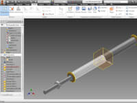
- Software used for this entry:AUTODESK INVENTOR
- Patent status:none