


The objective of this proposal of an ionized air motor is to improve the efficiency of the conventional motor by reducing the inhibiting factor which is the weight of its armature. My proposal of an alternative form of motor uses an armature made up of light weight plastic containers containing positively and negatively charged ionized air. The containers are moved by alternating polarities of the electrical plates that act as the stator of the motor. The voltages across these plates are alternated with use of relay logic circuits that uses two latching relays. The use of latching relays ensures that the relays maintain their state even if they are not activated. A sensor generates interrupts for the micro-controller that allows the micro-controller to activate the relays and change the voltage across the multiple plates.
The colored diagram shows the four distinct cycles that repeat periodically when the motor is working. The topmost figure with concentric circles shows all the four cycles with the first cycle being the innermost circle. The negatively and positively charged plates around the containers make them rotate in a clockwise direction due to interaction by virtue of electric forces. After the containers have almost covered one sector angle, in this case 45 degrees, the polarity of the stator plate’s changes i.e every plate now has the same polarity as its left hand side neighbouring plate had before. This causes the same effect by virtue of the configuration of the plate’s polarity to take place again and it continues in a periodic manner as long as the motor is running.
The four diagrams show the different cycles. The plates have been numbered for ease of understanding.
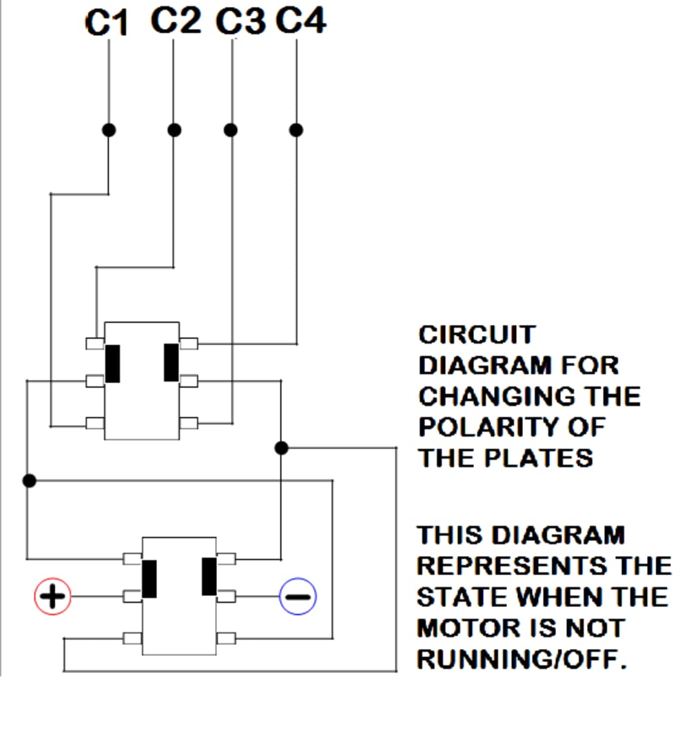
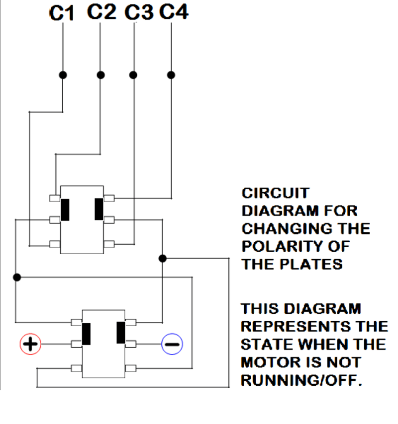
The next diagram show the latching relay configuration that change the polarity of the plates. The first separate diagram gives the skeleton of the circuit. The next block diagram shows the relay configuration during the four defined cycles. C1, C2, C3 and C4 are abbrevations to the group of plates that have the same polarity at a given time. There are four such groups defined as follows:
• C1::Neutral::Positive::Neutral::Negative
• C2:: Positive::Neutral::Negative::Neutral
• C3::Neutral::Negative::Neutral::Positive
• C4::Negative::Neutral::Positive::Neutral
The polarities present in each group repeat themselves periodically and the four junctions shown by a single line and a filled circle represent the connections from plates belonging to each group are taken together and combined together to a common junction. The other end of each combination of plate is grounded. The negative and positive external source voltage are shown connected to the relay at the bottom. The small filled rectangle represents which ends of the relays are connected. The topmost relay is activated by the micro-controller after each interrupt recieved from the sensor and the bottom relay is activated after every two interrupts from the sensor. The description of the exact mechanism of how the sensor interfaces with the m/c crosses the word limit but in a nutshell involves a method to detect when the container has covered almost one sector angle.
Like this entry?
-
About the Entrant
- Name:Anushka Goyal
- Type of entry:teamTeam members:Shahana Sharif
Anushka Goyal
Aniketh Jain - Patent status:none