
This is an attempt to lift water by using a piston cylinder assembly beneath a speed breaker on road. The ‘IN’ line of the cylinder will be connected to a reservoir on ground and ‘OUT’ line will be connected to a reservoir at a particular height with respect to the ground. The piston head will receive the vehicle tire. On passing the vehicle or a person, the piston will move down inside the cylinder and raise the water to required height. A helical spring will bring back the piston to its original position to receive its next stroke while the non-return valves at both IN and OUT lines will ensure the flow in correct directions.
At theoretically zero cost, the water is lifted and it can be used for various purposes like watering the plants around, irrigation besides highways etc. The same can be an attraction point for visitors if placed in an organisational campus.
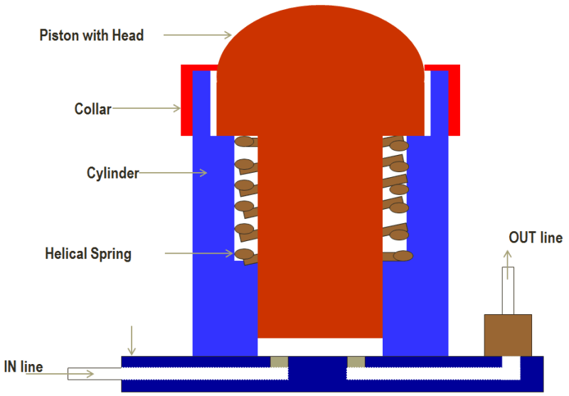
The device consists of a piston having a hemispherical head and a collar as shown in figure. It can be manufactured from mild steel with hard chrome plated bore. Threading is to be provided at the top 50 mm of the cylinder on which a mating mild steel cylinder collar threaded from inside will be tightened. The main purpose of the cylinder collar is to restrict the flying of the piston out of the cylinder due to spring force.
A carbon steel spring will rest inside the cylinder on a seat as shown. A bottom flange, which will have inlet and outlet ports with non-return valves, will be fixed to the cylinder by means of six Allen screws with a gasket. Oil ring is to be provided in the bottom of the cylinder to avoid leakage. After placing spring inside the cylinder on its seat, piston should be inserted in the cylinder, which should pass through spring, and the collar shall fit in the top recess provided in the cylinder. Collar shall always remain inside the top recess for some length to provide proper guiding when the piston is forced inside the cylinder.
Now, the cylinder cover can be tightened, and the hemispherical piston head shall project out of the cover from central hole provided in the cover as shown in the figure.
When a force is applied on the piston head, it moves down inside the cylinder thereby forcing all the available water out of the cylinder. The maximum downward movement of the piston shall be limited by providing a stopper (a steeped cavity) in the cylinder in order to prevent the spring to reach its solid length. Thus whatever may be the load, spring will never get compressed to its solid length there by preventing the spring failure. When the force will be released, the spring will bring back the piston to its original position and while doing this, water will be sucked inside.
A working prototype has been realized in past.
Like this entry?
-
About the Entrant
- Name:Sachin Wagle
- Type of entry:individual
- Software used for this entry:Unigraphics
- Patent status:none