
O.K. I'll list logic ( also view http://designdeskinc.com/Electric_Automobile.html )
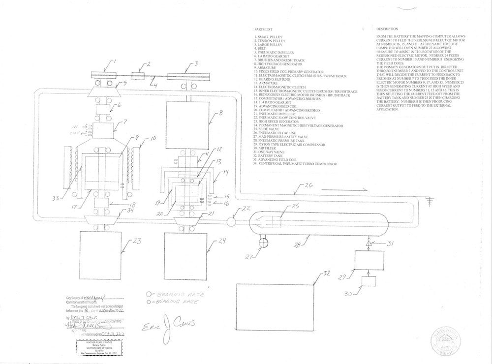
1. Power from the battery powers redesigned electric motor to 1000 r.p.m., permanent magnetic generator energizes field coils
2. Air pressure is released impaling the redesigned electric motor/ generator assembly flow reduces field resistance
3. The pulley on the end of the redesigned electric motor / generator assembly is driving another pulley on the compressor assembly at 1:2 ratio in tandem with pneumatic impeller and resistance of the 1:4 ratio gear set and current "pick up" (armature of primary generator)
4. Now 2000 r.p.m. into a 1:4 ratio gear set produces 8000 R.P.M. in the primary generator. current re-dumped to the primary generator internal electric motor
5. Angular conservation...add loading and resistance from 1:4 ratio gear set and high speed generator (also permanent magnetic) as an estimate input 5000 r.p.m.
6. So the compressors motor is driving at 5000 r.p.m. into a 1:4 ratio gear set sending the pneumatic compressor to 20000 r.p.m. at 2000 p.s.i. . You will find that the system operates on less pneumatic pressure it is filled with slightly greater pressure than resistance produced by the generating magnetic fields and ratio gear set.
7. Pneumatic flow post compressor impales an impeller listed in number 3 (pneumatic turbo compressor assembly). velocity reduces field resistance of both assemblies and increases the primary generators armature to est.+/- 40000 r.p.m. with current dumped to the primary generators inner electric motor causing the compressor to advance at greater rate. This cycle will continue to increase in power with speed governed by the mapping computer.
8. Current produced from the high speed generator (at 20000 r.p.m. feeds the redesigned electric motor ) then advancing the redesigned electric motor / generator assembly from it's 5000 r.p.m. with additional rotational force applied through magnetic pressure and current from the high speed generator to an addition of 5000 r.p.m. from electricity to the redesigned electric motor. The current from the battery is shut off and then receives charging from the high speed generator. The pneumatic velocity is then counteracting the resistance of the generators by velocity of 10,000 r.p.m.
9. Cycle is constant increase over unity extracted from high voltage generator. It's a circular thrust equation in which the variables increase.
10. Effect of electromagnetic clutch at high speed elongated power orbit because the high speed pneumatic flow is advancing. The system is designed to speed up when loading is placed upon the high speed generator because of reduction produced by pneumatic pressurized flow.
11. This system should demonstrate the forward advancement of magnetic pressure by compounding pneumatic velocity flow.
copyright released - open source - signed Eric Crews CEO / Founder Design Desk Inc.
( www.designdeskinc.com )
Like this entry?
-
About the Entrant
- Name:Eric Crews
- Type of entry:individual
- Patent status:none