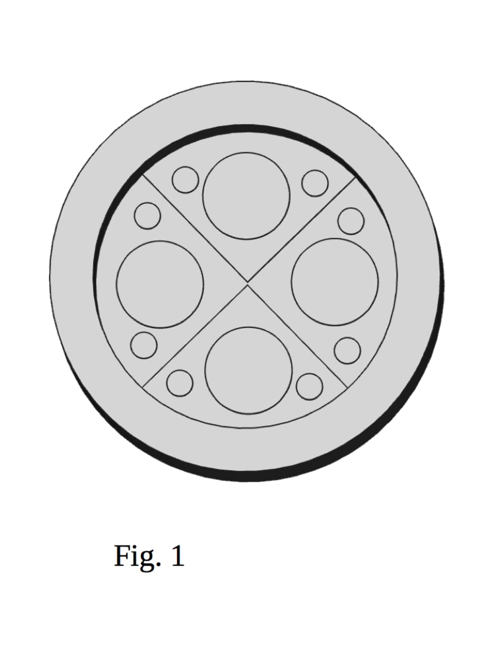
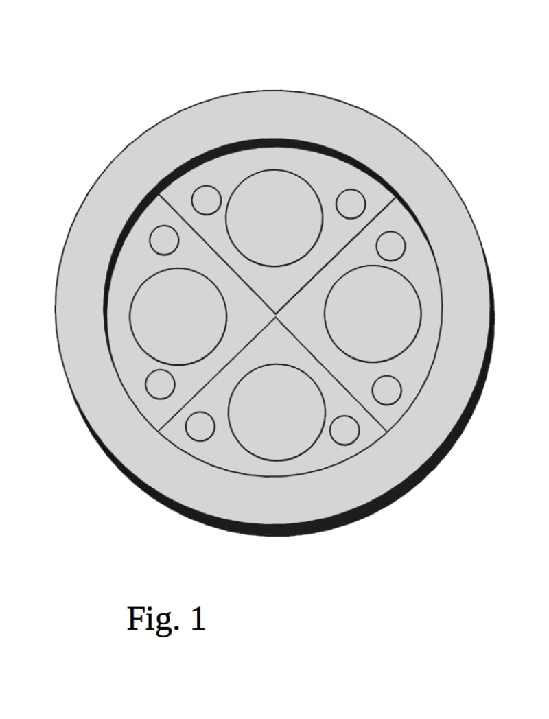

The cylinder diameter is typically a few times or more of the stroke. When the piston nears the end of the compression stroke, vertical ridges on the piston, in conjunction with almost mating vertical ridges in the cylinder head, effectively partition the combustion chamber into multiple combustion chambers.
Fig. 1 shows four partitions, each with a valve and two spark plugs.
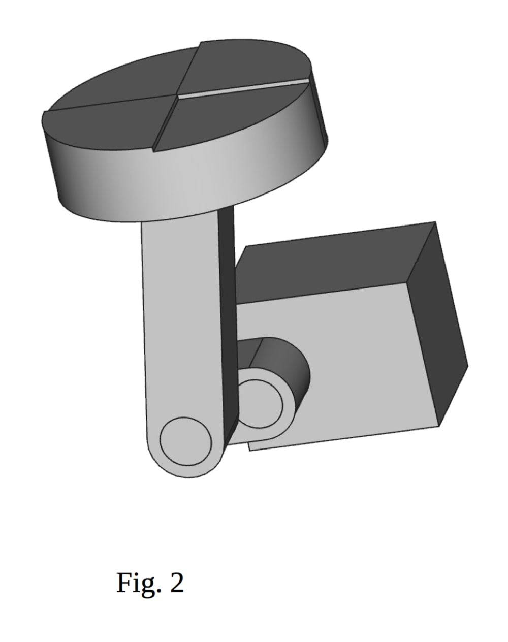
A rotary start stop mechanism is connected to an external flywheel. The flywheel (operating through the rotary start stop mechanism) supplies energy for compression and absorbs energy from combustion. The rotary start stop mechanism always stops at the same angle relative to itself. Rotating the mechanism about the crankshaft axis also rotates the engine crankshaft stop angle, varying the stopping point of the crankshaft, varying the stopping point of the piston in the cylinder, providing variable compression of the charge in the cylinder. The rotary start stop mechanism stops and starts the engine crankshaft at typically 25-60% of the upstroke.
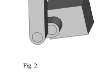
Fig.2 shows the partition ridges on the top of the piston, the connecting rod, the crank throw and the rotary start stop mechanism.
In a spark ignition engine, this allows the compression ratio of a smaller cylinder. For detonation like combustion of lean mixtures operation, the partitions can be ignited at varying times, somewhat averaging the overall pressure rise on the piston.
Expansion proceeds to BDC(bottom dead center), providing over expansion. The exhaust valve (s) in the cylinder head open prior to BDC. After BDC, the upstroke continues to the crankshaft stopping angle. Note that with over expansion, the blowdown is lessened. As the blowdown is ending, adjacent poppet valves for inlet open with the flow directed towards the cylinder wall by angled ports and/or shrouded valves. This provides a flow towards the cylinder wall, down, back across the piston, pushing the combusted gas out of the poppet exhaust valves. The intake and exhaust valves close while gasoline or a gaseous fuel is injected. The injection only begins once the risk of fuel escaping out the exhaust valve(s) is past.
For larger cylinders with room for more valves, the inlet poppet valve(s) in the cylinder head adjacent to the cylinder wall, open with the flow directed tangential to the cylinder wall. This provides a swirling flow about the cylinder axis, crowding the combusted gas out of the more centrally located poppet exhaust valve(s).
Part load operation is by varying the frequency of engine cycles, not by reducing the power per engine cycle. The engine cycles can be at near maximum thermal efficiency. One or more engine cycles are skipped by leaving the crankshaft stopped at the crankshaft stopping angle for one or more flywheel revolutions. Note that this allows more time for scavenge.
Expected benefits include excellent part load efficiency, less friction because of less ring-piston sliding friction, less heat loss to the cylinder wall(s) (as compared to a multicylinder engine) and more efficiency because of the over expansion.
Like this entry?
-
About the Entrant
- Name:Stanley Lass
- Type of entry:individual
- Software used for this entry:python
- Patent status:pending