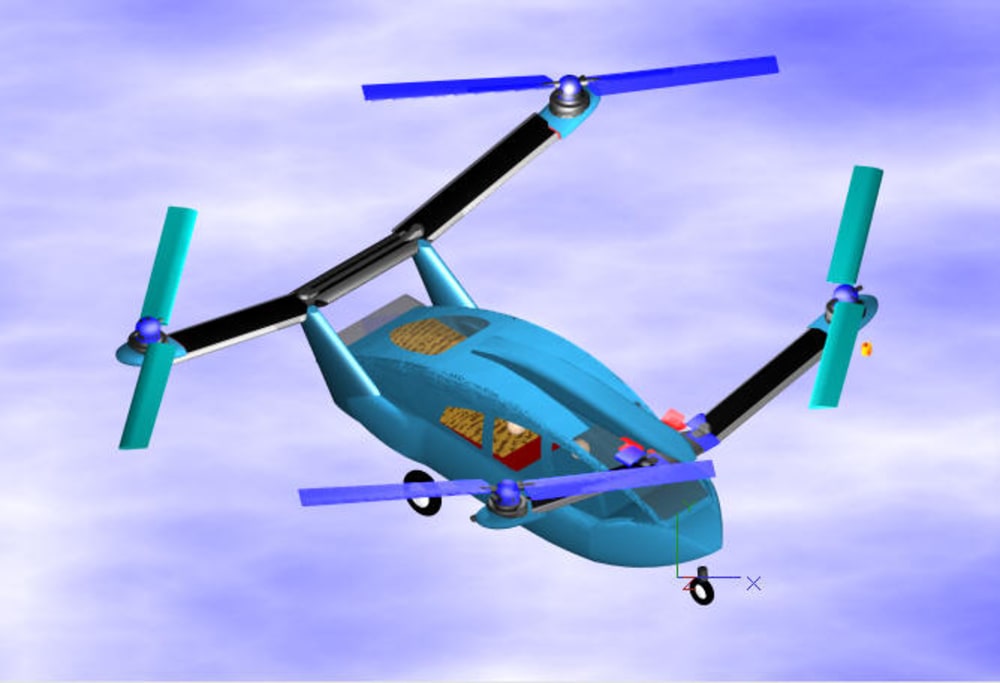
The technology levels for the Quad Fold Helicopter (QFH) are based on those existing around the year 2010. The levels at 2050 can be assumed advanced some from those levels. An important technology feature is the rotor drive motor at the end of each of the folding booms. The motor is taken from the published spec of the Protean electric wheel motor having a peak output power of 100 HP at a shaft speed of 1000 rpm. Other technology levels include carbon composite airframe and rotor blade structures.
DYNAMIC SYSTEMS Continuous electric power is provided by a hybrid engine-generator set aimed at economically providing the lightest weight electrical power generation from its fuel. Lithium battery packs are located in the rotor support booms and are electrically networked together among the four booms. They are primarily used for bringing electrical systems on line and starting the hybrid power plant. Sufficient battery power is available for safe landing from cruise altitude in the event of fuel starvation. Garage stowage of the QFH does not require rotor blade folding. Rather, the stowage folding is done by the rotor support booms that are pivoted from the body structure to stow the rotors side by side over the cabin roof. The quad arrangement uses four 14 ft diameter rotors. At the rated motor speed of 1000 rpm, the direct drive rotor tip speed is typical for many helicopters. No rotor drive gear boxes are needed. No tail rotor is needed. When stowed, this rotor diameter allows the 17 ft long five-place body to fit a residential garage. Each rotor hub provides see-saw flapping and two blades with collective pitch (similar to two-bladed tail rotors). No cyclic pitch is required because the quad rotor configuration can generate pitch, roll, and yaw moments with collective pitch rotors only. The multiply redundant fly-by-wire control system is modeled somewhat after the ubiquitous small quadrotor helicopter drones that synchronize speeds of four rotors but use rpm variation control between rotors rather than collective pitch variation for control. Collective pitch provides a faster response for thrust variation at the larger size for people-carrying quadrotors than would commanding rpm variation of different rotors. The resulting total rotor disc area retains the low disc loadings at 5-place vehicle gross weights that are suitable for autorotation landings.
STRUCTURAL SYSTEMS The cabin layout is for a 5-place body having front and rear doors plus a hatchback that allows carrying 4 x 8 ft building panels. (By leaving the hatchback slightly open longer panels would be accommodated.) The landing gear arrangement is tricycle and retracts only partially. The aft main wheels are driven with low-powered motors and are used for ground taxi. The tricycle gear can “squat” to fit within garage 7 ft overhead clearance and can power taxi either extended or “squatted”. The engine-generator bay under the cargo floor houses the hybrid power plant (400 - 500 HP) that outputs 400 volt power for distribution to the four rotors via cable conduits in the booms.
Like this entry?
-
About the Entrant
- Name:John Detore
- Type of entry:individual
- Software used for this entry:TurboCAD Pro
- Patent status:none


