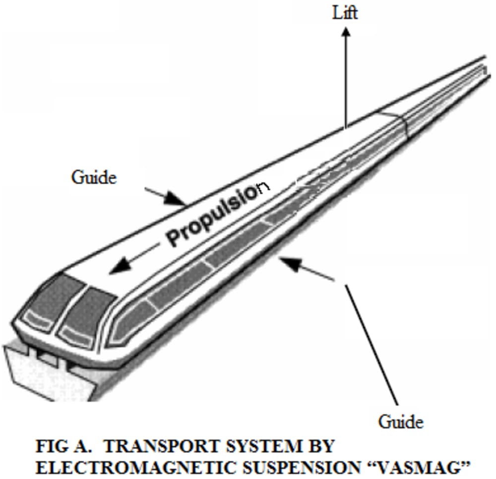
The VASMAG transport system uses the principle of electromagnetic repulsion, in which the rail is constructed with non-magnetic conductive materials, (aluminum or copper), so that large superconducting magnets can be used, naturally more power is required to energize them, but can allow a greater inter-iron with a simpler control than in the previous process, the system is self-controllable, because if for some reason the inter-iron is reduced, the repulsion force is increased, with which the vehicle tends to take its original separation, nevertheless requires additional rails to hold the vehicle until the minimum lift speed is achieved.
This type of mass transport (Fig. A) can be used in long slopes, uses a linear reluctance motor to achieve the 3 requirements for movement (propulsion, guidance and lift).
The secondary rail is formed by a concrete track (C) within which are fixed the armor or cores (N) of sweet iron. These are distributed longitudinally on each side of the track (Fig. B) and are spaced regularly. Above and below the track (C) are placed parallel and longitudinally thereto, the electromagnets (I) of the primary (or fixed stator) in the vehicle.
Each set of four electromagnets (AA'aa ') forms a magnetic circuit that is closed through the inter-irons and two armatures of the track (Fig. C). The section of the poles of the electromagnets is equal to the section of the armatures. The poles are separated from each other by a certain distance. There is another distance between the armatures.
When a set of 4 electromagnets (or phases) is energized, a pulling force is generated with the closest armatures, giving rise to three components Fx, Fy, Fz, which can respectively to propel, guide and support the vehicle. These forces are paramagnetic and normal to the armatures, and to be able to propel the vehicle these must be discrete, ie, the conductive band of the linear induction motor can not be replaced by a continuous band of iron. This force can be expressed as the spatial derivative of the mutual energy between the electromagnets and the armature.
F(x,i) =( i²/2) (dL/dx)
Where
Fx : Longitudinal component of the force propelling the vehicle [N]
E : Electric field [V/m]
L : Vehicle inductance for different distance values [H]
The force component Fy, appears when the primary (or stator) moves laterally with respect to the track or rail, thus guiding the vehicle. The force component Fz, contributes to the lift of the vehicle.
In the electronics control scheme of Fig. D, the control signal generated by the microcontroller, for each electronic switch, passes through an optical coupler which isolates the low-level electronics stage from the power electronics stage. The output signal of the optical couplers is applied to a driver, which allows controlling the floating transistor and having a higher current, to increase the switching speed of IGBT transistors used as power switches. The position of each of the electromagnets relative to the armatures mounted on the rail is detected by a magnetic sensor.
Like this entry?
-
About the Entrant
- Name:Gustavo Vasconez
- Type of entry:individual
- Software used for this entry:AutoCAD, Proteus Design Suite.
- Patent status:none


