


The aim of the project is to create a flexible engine that can run on gasoline as well as steam, just by the change of the camshaft and cam-drive gear modification.
Since this project mainly focuses on utilising the scrap IC engine conversion to steam powered double acting engine, lubrication and other fuel injection complexities can be avoided in steam engine.
From this work estimated power up to 5kW will be generated.
The valve timing of engine is different in 4 stroke & 2 stroke. To rectify this we first analyzed the firing order of the engine. The firing order came out to be 1-3-4-2.
For working of double acting steam engine, any 2 pistons should move in pair. This condition is satisfied, if the cam orientation is being manipulated.
How to convert a 4 Stroke engine into 2 Stroke engine?
For this we change the GEAR RATIO of crankshaft & camshaft from 2:1 to 1:1.
To solve this problem first we studied the orientation of cam lobes present on the camshaft & they were found to be at a phase difference of 90˚. So they were not oriented as desired.Thus we proceed further with our first option. But it failed. Why?
Because of materialistic property of camshaft (hardened steel). So it was not possible to modify the previous shaft.
Thus we come to the next option of using the REED VALVE.
But it also failed as it fulfilled the exhaust conditions but not the inlet (enough pressure and proper valve timing and there was a need of proper cut-off.)
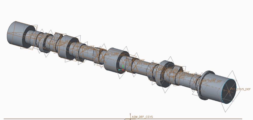
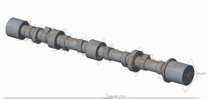
Then the last option left was to design and manufacture the new camshaft with proposed designed. The new design is as:
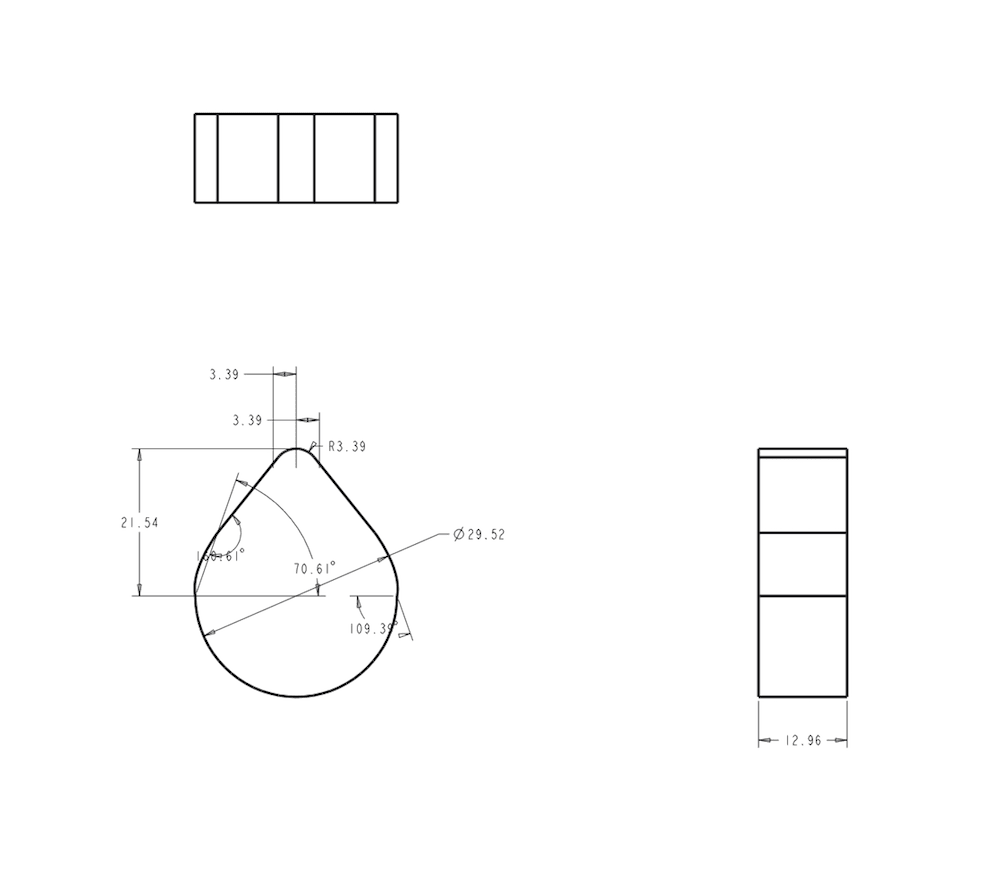
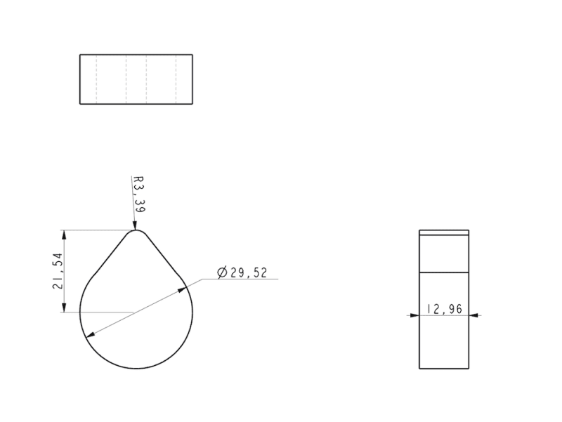
Design of camshaft
First the cam orientation was changed i.e. to make engine double acting pistons 1 &3 should move in same direction while piston 2&4 should move in opposite direction to piston 1&3. Since the design of crank shaft of engine is so that the pistons move in desired direction as explained above. To set the valve timing orientation of cams is designed as the orientation of inlet & outlet cams of piston 1&3 is opposite to the piston 2&4. Then 90 degree cut-off is set to inlet cam. (Reference- Principle of steam engine by Terrell Croft). Then outlet cams are designed to open the exhaust valve for 180 degree. All the cams are designed through tangent method.
power calculations
By using Formula,
h.p. = plAn/33000 (h.p.)
Where,
p=mean effective pressure in psi (pd/sq inch)
l= stroke length in feet
A=area of piston (inch sq.)
n=revolution in rpm
Assume at standard condition mean effective pressure (p)
inside engine is 4 bar.
p=4 bar= (600/41) x4 psi
l=142mm =0.5 feet (approx.)
A= (π/4) x (3.182’’) 2
n=250rpm
h.p. = {(58.5) (π/4) (3.182’’) 2(250)\33000} x2
= 3.52x2 (h.p.)
= 7.045 (h.p.) or 5.255 KW
Like this entry?
-
About the Entrant
- Name:Zoeb Ali
- Type of entry:teamTeam members:ZOEB ALI SHIVBODH AHIRWAR RAHUL KUMAR
- Software used for this entry:CREO
- Patent status:none