

The object of this invention is to create an energy efficient rotary magnetic motor. The world is desperately looking for a clean energy alternative as we transition from fossil fuels, one that uses less electric current than conventional electric motors. By effectively using the permanent magnets in the rotor to react with the permanent magnets in the stator, to drive the rotor using permanent magnets only for approximately 300 degrees of one turn of the rotor, for the remaining 60 degrees the permanent magnets in the rotor will react with the energized coil in the stator to keep the rotor turning in a given direction. When compared with a two stroke petrol engine which has a power stroke of from ignition to the exhaust approx. 60 degrees, but then is consuming energy for the remaining 300 degrees while compressing the incoming fuel, fuel transfer and final stage compression.
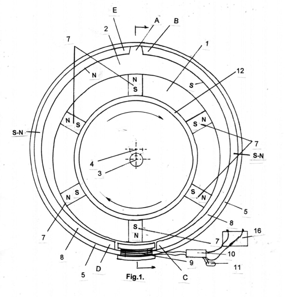
The operation of this invention is if we look at Fig.1. the permanent magnet on the rotor closest to the energized coil, which has just changed to a north magnetic pole, the permanent magnet has a North magnetic pole facing out wards, the permanent magnet on the rotor will be repelled away from the energised coil to point “D” on the curved permanent magnet in the stator, and because the gap “A” between the permanent magnet in the stator, and the permanent magnet in the rotor is increasing, the permanent magnet in the rotor will move in the direction of the increasing gap. Like magnetic poles repel, so the permanent magnet on the rotor will reach point “E” on the permanent magnet fixed to the stator, where it will be attracted to point “B” which is an opposite magnetic pole, and as unlike magnetic poles attract, and the gap between the magnet in the stator and rotor is decreasing, the magnet in the rotor will move to point “C”. At this point the magnetic pole on the energised coil will be an opposite magnetic pole, and the permanent magnet on the rotor will move until it is at the centre of the energised coil, the energised coil will now change to a same magnetic pole as the permanent magnet in the rotor, and the cycle repeats.
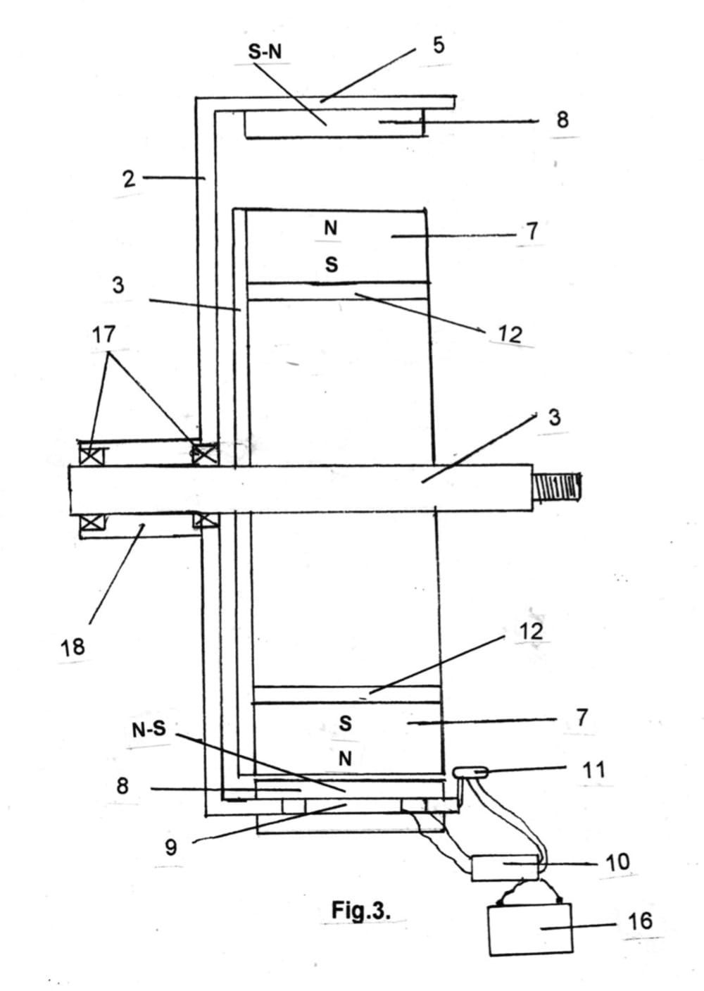
In the drawings, Fig.1. shows a plan view of the Rotary Magnetic motor, while Fig.3. shows a side view of Fig.1. for a single unit using one energized coil in the magnet backing ring in the stator.
Like this entry?
-
About the Entrant
- Name:John Ettridge
- Type of entry:individual
- Software used for this entry:none
- Patent status:pending