


Cylinder Deactivation is a well-known automotive and diesel concept employed for decades to improve cylinder pumping losses and improve fuel economy. It does so by shutting off both fuel injection and valve motion to specified cylinders during light load conditions. A non-firing cylinder creates a reduced cylinder gas pressure allowing excessive oil to enter the combustion chamber via current piston ring design. This reverse oil flow contributes to a significant increase in oil consumption, added ash deposits and foreign particulate matter contaminating the emission after treatment systems. This anomaly is independent of the fuel being burned, i.e. diesel, gas, hydrogen, other alternative fuels.
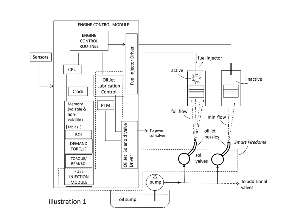
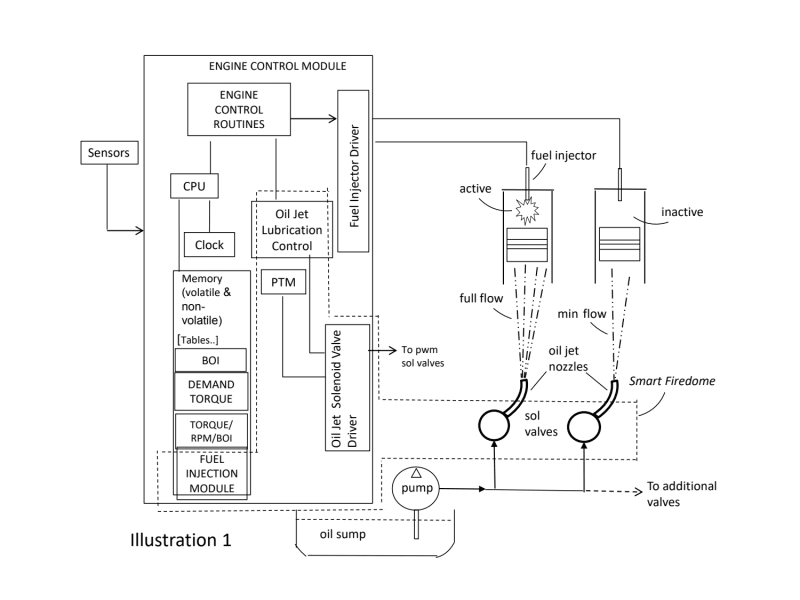
Illustration 1 satisfies these aforementioned needs by a patented (US 11, 421,565 B1) concept referred to as Smart Fire Dome and is our Next Gen Soot Reduction Concept. It senses the fuel injection “shutoff state” of each cylinder independently during deactivation and reduces the directed cooling/lubricating oil from the sump, through the oil jet piston nozzle solenoids, to the bottom side of both active and inactive pistons. Two cylinders of this engine are shown in both an active and inactive combustion state, controlled by a traditional ECM incorporating cylinder deactivation capability. Engine load requirements translate to a specific table-driven fuel-injected pulse width of injected fuel, whereby this concept mimics this pulse width and translates to a corresponding duty cycle pulse width for managing oil delivery to cool/lubricate the piston(s). The control for producing these duty cycle pulses for driving the pulse width modulating these solenoid valves is represented within the Smart Fire Dome block. Thereby, capturing all elements not incorporated in traditional cylinder deactivation strategies.
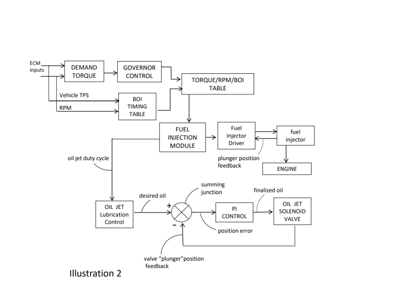
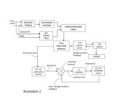
Illustration 2 depicts the closed loop control in schematic block fashion, whereby the Oil Jet Lubrication Control Block receives a continuous updated “oil jet % duty cycle value” representing fuel injection on a per cylinder basis. The desired oil feed forward value to the “summing junction” is evaluated through a set of software “lubricating/oiling rules”. A full-high-load on the piston translates to (81-100%) duty cycle, wherein a (0-20%) duty cycle represents deactivation/cutout/idle conditions. Three other middle range categories of desired oil values exist, including medium-high-load, medium-low load and low-load flow quantities. A proportional-integral control scheme with each solenoid valve preferably configured for armature or plunger position provides the needed feedback control element to the summing junction.
Illustration 3 is a photo of the prototype bench setup of an analog/digital hardware control system for one cylinder, driving a pwm solenoid displaying a typical duty cycle waveform.
- Compliments conventional cylinder deactivation concepts for better meeting the latest stringent EPA emission standards. On February 7th, 2024, the EPA mandated a stronger soot particulate- matter reduction.
- The on-going lawsuits to penalize elevated oil consumption, soot and particulate matter levels, provide a stimulus to develop this over-looked strategy.
- Reduces oil from entering the EGR valve.
- Helps reduce piston dome “Super-Cooling” issues.
- Reduces engine oil consumption during cylinder deactivation.
- Extends oil change intervals
- Reduces ash and particulate matter.
- Minimal cost upgrades to traditional ECM hardware/software.
Video
-
Awards
-
 2024 Top 100 Entries
Like this entry?
-
About the Entrant
- Name:Michael Holihan
- Type of entry:teamTeam members:
- Patrick Derbin