


Wireless sensors are sometimes located so remote that replacing batteries is not an option. Such applications often turn to energy harvesters. Energy Harvesting (EH) also known as energy scavenging for small electronic and low power electrical devices uses ambient energy to provide electrical power, eliminating dependency of battery power, thus they work autonomously for years. Therefore, economical benefit from EH will be large and it can be ubiquitous worldwide.
In general, applications by EH sources like light, vibration, RF, thermal or chemical/biological are not only low power (in micro to milli watt level) — they are at low voltages. Since most current wireless sensors, including power conversion circuits, require 2+ volt range, we have two possible ways to meet those application requirements. One, the harvested voltage must be boosted and transfer energy as efficiently as possible. Two, the application requirement must buck down to subthreshold level to match with the harvested voltage. Since the second option involves newer chip designs and it is complex, the current proposal will focus on the first option.
In theory the systems and methods using multiple energy generators connected to the same energy harvesting circuit should result in more energy. However, if multiple sources are attached to the same circuit in an attempt to produce more electric energy, the energy loss will be very high and there will be less energy harvested than if a single source was used. The main reason for this is impedance mismatch in circuits that consumes all or a part of generated resource. Also, further losses occur due to the destructive electric signal interference results in less energy available. For these reasons, traditional single energy management circuit can only handle one energy generator at a time.
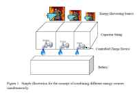
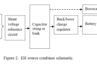
In order to overcome these deficiencies an approach of combining independently harvested energy from multiple generators is considered (see Figure 1). Similar to previous studies, each transducer can be tuned to the maximum power point tracking (MPPT) by a simple analog method, which is low cost for mass production. Instead of using supercapacitors, each subsystem is connected to a capacitor bank with a series of ordinary capacitors (see Figure 2). This way the harvested energy is temporarily stored in these capacitors before the master controller simply rearranges the capacitor array for storing in a battery. The reason of using the capacitor bank is utilizing a fact that the weakest capacitor in the string gets charge up first even small amount of energy harvesting. Use of an analog energy management technique with shunt voltage reference (instead of a digital MCU) and selection of appropriate capacitor size may improve cold booting. In addition, the proposed system addresses the following issues.
• Avoid using supercapacitors because concern for the high leakage in supercapacitors and charging characteristic near depleted condition
• Minimizing residual charge, i.e., reducing stored energy below the threshold voltage
• Widening the charging time period by lowering the harvesting power threshold (voltage, current). For example, thermal, wind and/or RF sources can take over during the time solar is not effective.
Like this entry?
-
About the Entrant
- Name:Hiroshi Ide
- Type of entry:individual
- Software used for this entry:N/A
- Patent status:none