
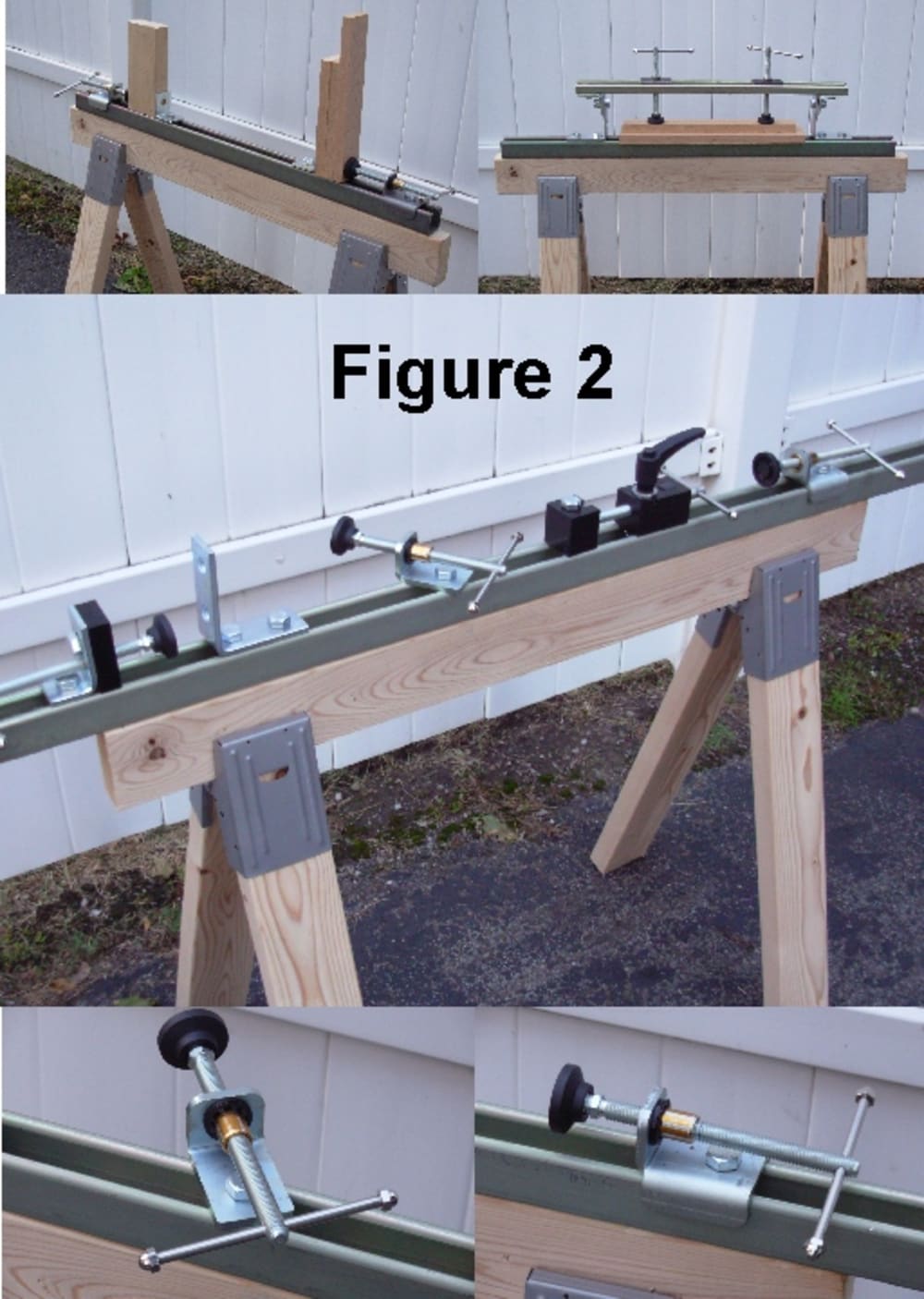


The strut channel bar clamps (figure 1) utilize a commercially available structural member (strut channel) that for years was used for hanging HVAC, pipes/conduit and other industrial components. The two parts of the strut channel bar clamp are the force imparting component herein known as the “clamp block” and the force supporting structure known herein as the “clamp stop.” Current clamps available in the market are made using bar stock, pipe and specialized structural members as their main support structure. These clamps are very limited in that the “clamp block” is rigidly fixed to one end of its’ structural member. In the case of the bar clamp, the user is limited to fixed lengths of 6”,12”,18”, 24” etc.
The strut channel clamp can be made using available strut channel accessories, formed heavy gauge sheet metal and/or machined components. All versions of the strut channel clamp are compatible for use with strut channels available in most home improvement stores. The strut channels are highly versatile, relatively inexpensive, and can often be cut to desired lengths with a hack saw.
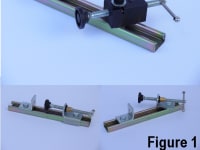
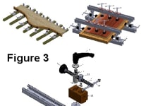
A primary advantage of the strut channel clamp is the ability to position the clamp block and clamp stop anywhere on the strut channel. All versions of the clamp take advantage of the fact that the open side of a typical strut channel provides an endless adjustment slot. The side opposite the open side of the strut channel (bottom) has either slots or holes. These features make it possible to mount the strut channel to sawhorses or shop tools (Figure 2) or make special jigs and fixtures (Figure 3).
Referring to the version of the strut clamp on the center of Figure 1, The clamp block has a threaded post that is the component that produces the clamping force onto the work piece. The threaded post has a T-shaped feature in which a post slides inside the threaded rod in a direction that is perpendicular to the longitudinal axis of the threaded rod. A so-called “quick nut” (US patent no. 5,898,974) feature, when pressed, releases the threaded engagement of the threaded post with the clamp block. The body of the clamp block that supports and guides the threaded post has a flat bottom and is secured to the strut channel using a clamp pin that has a slot large enough to allow the threaded rod to pass through it. The clamp pin has threaded features on the ends of it. One of the ends is engageable with a lock handle, while the other end secures a rounded channel nut, so that turning the lock handle secures and locates the clamp block to the strut channel. With the clamp block rigidly located to the strut channel, the threaded rod is still able to move freely, allowing the clamping action to take place. Because the bottom of the clamp block body is flat, the entire clamp block is capable of rotating 360 degrees about the axis of the said clamp pin. Patented
Like this entry?
-
About the Entrant
- Name:Michael Kelly
- Type of entry:individual
- Patent status:patented