


The proposed apparatus realizes inspection of optical members for cosmetic defects being surface flaws and inclusions. Plenitude of efforts is being made to develop methods and machinery for objective testing optical members prior to their utilization (e.g., patents: US 4,841,139; US 3,892,494; US 6,075,591; US 9,513,215; etc). Tiny optical defects scatter photons in azimuth-dependent manner mainly forward and backward in a narrow range of angles. The major problem of existing systems is an impossibility of proper detection of light scattered at small angles and their sensitivity to optical member parameters and to defect location and orientation, making the systems not reliable and susceptible to high false rejection rates.
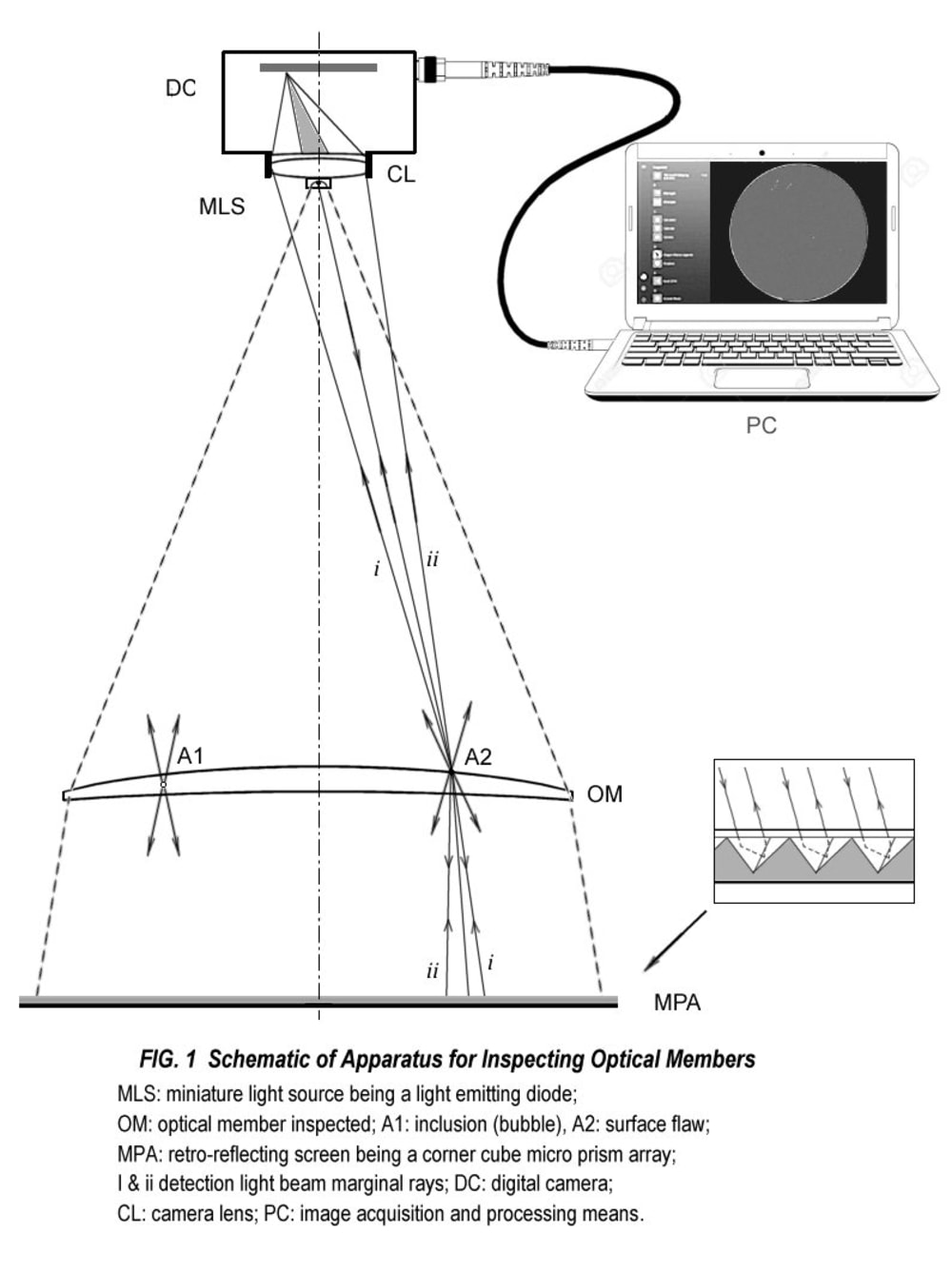
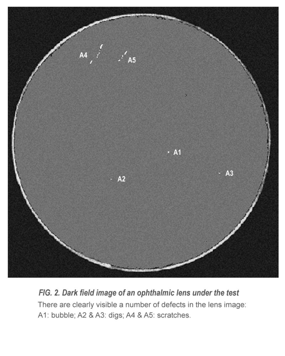
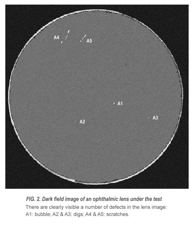
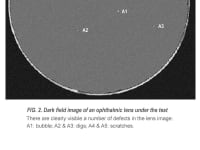
The apparatus is schematically depicted in FIG. 1. Illuminating light from a miniature light source, disposed on the optical axis in front of a lens of a digital camera, travels through an inspected optical member to a retro-reflecting screen that may be a corner cube micro prism array, is retro-reflected by the last, propagates back to the light source along the same optical paths as the incident light, and is further blocked by the light source effecting now as a light stop. The direct and retro-reflected light provides double-path illumination of each point of the optical member at angles close to its observation angle. Whenever illuminating light meets any defect in the member, it is scattered forward and backward in a narrow light cone. Photons scattered at small angles to the direct and retro-reflected light path solely arrive to the camera lens aperture. The camera detects the light scattered by defects providing thereby an optical member dark field image, similar to one depicted in FIG. 2. The lens defects have a high contrast and are easily detectable. The row image data is transferred to the acquisition and processing means, for detection of defects, their classification, measurement and localization.
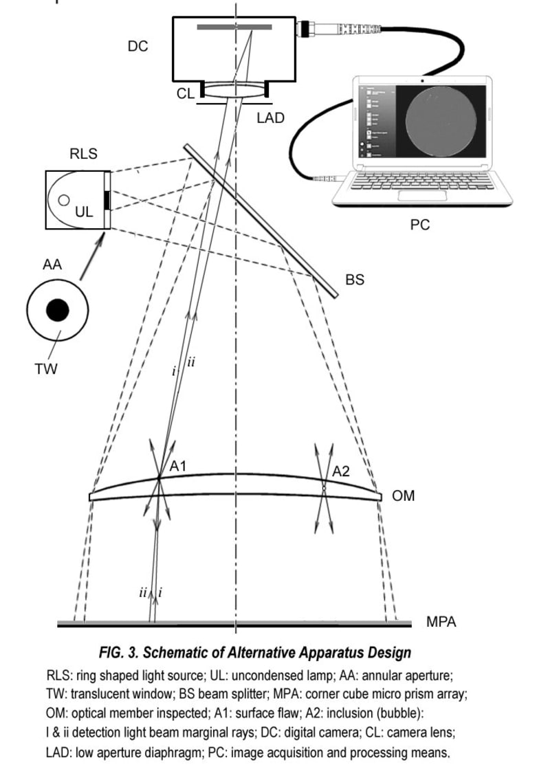
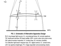
Alternatively, the light source and camera may be separated spatially with a properly aligned beam splitter, directing illumination light towards the optical member and passing imaging light towards the camera. The camera lens must have an annular aperture with a light stop on its axis. An alternative apparatus depicted in FIG.3 comprises a ring shaped light source with the central dark area surpassing opening of the camera lens diaphragm, and said beam splitter.
The proposed imaging apparatus is seen as a cost effective instrument, attractive and affordable for visualization and detection of optical (cosmetic) defects not only in mass production of optical components, e.g., in ophthalmic industry, but it may be adopted for detection of surface and interior (with NIR illumination) defects and contamination in semiconductor industry. Therefore, it has a great market potential, because in the United States only, there are above 180,000,000 glass wearers, so optical labs and glass manufacturers would be interested in the product. The system may be manufactured of off-the-shelf components mainly. Material cost of the built prototype is below $2000.
Like this entry?
-
About the Entrant
- Name:Peter Vokhmin
- Type of entry:individual
- Software used for this entry:ZEMAX, MathCAD, ImageJ
- Patent status:pending