


Novelty
My goal is to build a more human-like robotic head, using this electronic control system, to enable friendly human-robot interaction, which means that it is programmed to react as a human would. For example, for mimicking being surprised, the system is programmed to perform a jerk movement of the head, which is a common reaction for being surprised. In addition to the jerk movement, 20 other movements that mimic human reactions have been programmed.
System Description
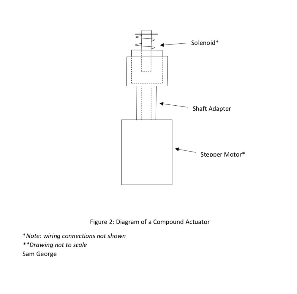
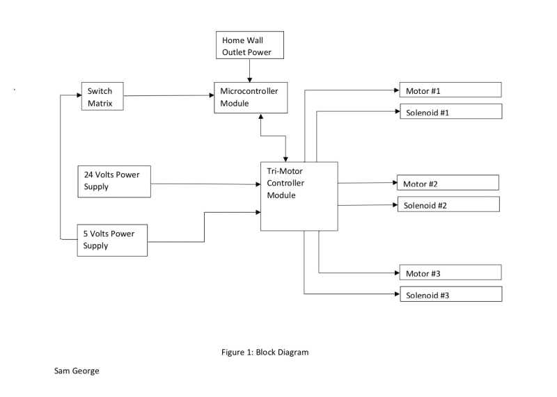
The electronic system consists of the following components: the microcontroller module, the Tri-motor controller module, the switch matrix, 3 bipolar stepper motors and 3 solenoids. Through the position of its 8 switches (where each switch is active low) the switch matrix directs the microcontroller to drive the motor controller board, which in turn drives the stepper motors and the solenoids in a specific sequence in order to mimic various human-like reactions. Each stepper motor and each solenoid can be driven independently. As shown in Figure 1, the motor controller board requires a 24 Volts DC power supply and a 5 Volts DC power supply to operate because each integrated H-bridge driver IC has a digital logic circuit and a power circuit. On the motor controller board, there are three stepper motor controller ICs, where each controls one integrated H-bridge IC. Each H-bridge IC, in turn, controls its corresponding stepper motor. Each solenoid is driven by a low-side NMOSFET, which is controlled by the microcontroller. In the implementation of a robotic head, one stepper motor is mechanically coupled to one solenoid, via a shaft adapter, to form a compound actuator. The compound actuator is the fundamental element of the robotic head. As shown in Figure 2, the solenoid is fixed onto the shaft adapter. The adapter then is fixed onto the shaft of the motor. Each compound actuator is assigned an axis (x-, y-, or z-) on which the corresponding motor’s shaft will rotate. For example, one actuator is assigned the x-axis, where the motor’s shaft will rotate (clockwise or counterclockwise) on the x-axis. The actuators are mounted onto a wooden frame, as shown in Figure 3, and support the headpiece.
Application of System
My system can be applied to Research and Development purposes.
Component Procurement/Manufacturing Feasibility
I procured the system components in the following manner. I procured the stepper motors from Lin Engineering. I procured the solenoids from Amazon. I procured the microcontroller board from Axiom Manufacturing. I designed the PCB layout of the Tri-motor controller board, using layout software (provided by ExpressPCB) and evaluated and assessed all the ICs and all the values of the circuit components, such as the resistors, the capacitors and the diodes. The circuit components and the components for the switch matrix were procured through an online electronics distributor. And the Tri-motor controller PCB was manufactured by ExpressPCB. After obtaining the Tri-motor controller board, I hand-soldered all the components; however, this can be performed by a PCB Assembly provider or a specialty electronics manufacturer.
Like this entry?
-
About the Entrant
- Name:Sam George
- Type of entry:individual
- Patent status:none