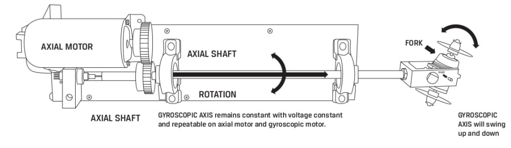

Gyroscopic procession device consists of a main DC motor, “axial motor,” driving a hollow shaft with a fork mounted gyroscope. The main axial motor and gyroscopic motor are precisely controlled by DC voltage with precise control of RPM. Reversal of polarity reverses direction of the tilt of the gyroscopic axis. The main axial motor is geared parallel to the “axial shaft” which is hollow containing 2 electrical leads extending down the axial shaft from the inline rotary contact ( MercotacTM ) to the gyroscope motor. This gearing allows the 2 lead axial shaft to be offset from the motor allowing the rotary contact to be co-axial with the axial shaft. The axial shaft is held in place by two bearings. At the far end of the shaft is a fork which has the gyroscope in a pivot (a one direction gimbal ). The gyroscope consists of a DC electric motor with each shaft of the electric motor extending to a gyroscopic disc on each side of the motor.
Fig.1
In operation, the main axial shaft rotates in one direction, and one pole of the rotating gyroscope will go up and the other down. This tilt gives an angle to the gyroscopic device in constant relationship to the main axial axis- herein described as the gyroscopic angle. This angle is proportional to the voltage on each DC motor and is repeatable with the same voltage ( RPM ) on each motor. With change in polarity of either motor, the same pole of the gyroscope will tilt in the opposite direction. With voltage applied to the gyroscopic motor, one pole will swing upward to the full excursion in small precise increments and go the opposite direction with polarity reversed. This gyroscopic axis will swing to perpendicular to the axial axis at zero voltage. For example, a ramp of voltage to the gyroscope (from +6 v. to zero to -6 v. at 20 rpm on the axial axis) will give a full pivoting action of the gyroscopic axis.
Addition of a third lead down the axial shaft allows a lead to be brought to the gyroscopic assembly to power a laser coinciding with the gyroscopic axis. This provides a circular scanning motion of the laser or lidar (perpendicular to the axial axis). With a change in azimuth of the circular gyroscopic axis, 3 dimensions can be scanned. The traveling laser dot can be electronically distanced with an electronic theodolite. This consists of two imaging devices separated by distance mounted in line with the gyroscopic axis or separately from the gyroscopic device. Offset between the images is a geometric measurement of the distance from the theodolite providing all 3 dimensions for computer reconstruction.
Alternately, the gyroscope can be substituted with a round cutting head. This would allow a spherical tumor to be cut out through a much smaller hole. The same action would allow for “belling” of a shaft as a base of a concrete pile for elevated roads and bridges.
Video
Like this entry?
-
About the Entrant
- Name:Sam Spikes
- Type of entry:individual
- Software used for this entry:none
- Patent status:pending