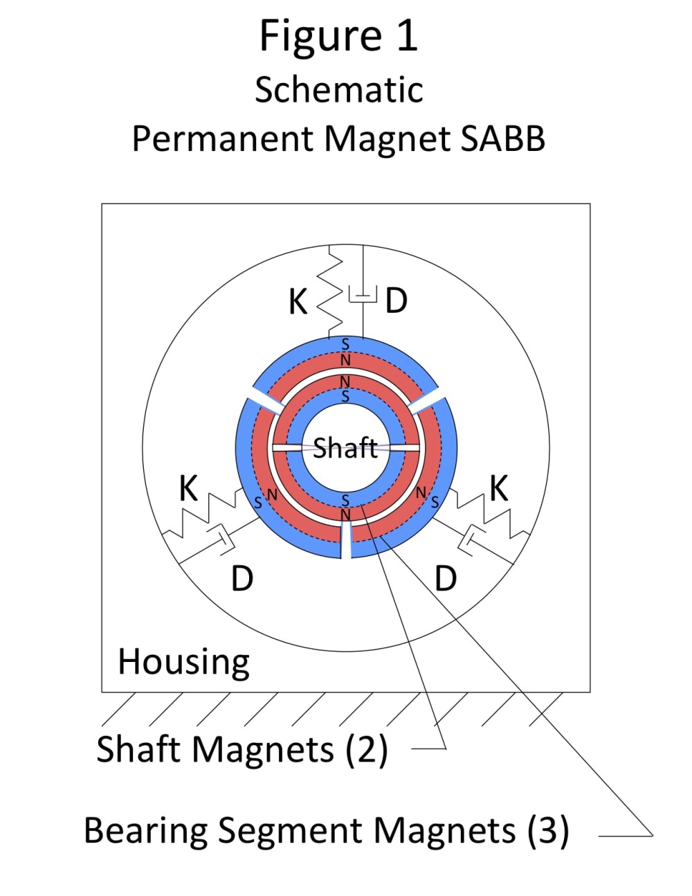


The Self-Adjusting Bushing Bearing (SABB) described in US Patents (8,870,459, 9,790,988, and 9,995,342 (Reference: https://cadventuresinc.wixsite.com/sabb/patents ) shows the many benefits of providing resiliency in a bushing bearing by segmenting the bushing bearing into three equal segments which are spring-loaded against the Shaft. Such resilience can also stabilize the use of permanent magnet repulsion to create a Magnetic Levitation Bushing Bearing (MLBB) as shown in Figure 1.
In 1842 British mathematician, Samuel Earnshaw, demonstrated that you could not make a magnetically levitating bushing bearing through the use of permanent magnet repulsion alone because the magnetic force falls off non-linearly as an inverse square of the distance, known as the “Earnshaw’s Theorem”. For example, if you double the gap between repelling permanent magnets, the repulsion force is only 1/4th as strong. However, when configured as shown in Figure 1, in which the inside surface of the Bearing Segments are the same permanent magnet polarity as the outside surface of the magnets attached to the Shaft, a Springy Element can be selected to provide a stabilizing resilience to overcome Earnshaw’s Theorem.
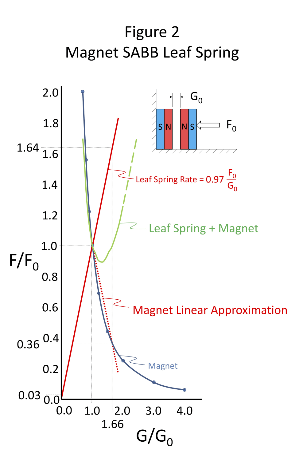
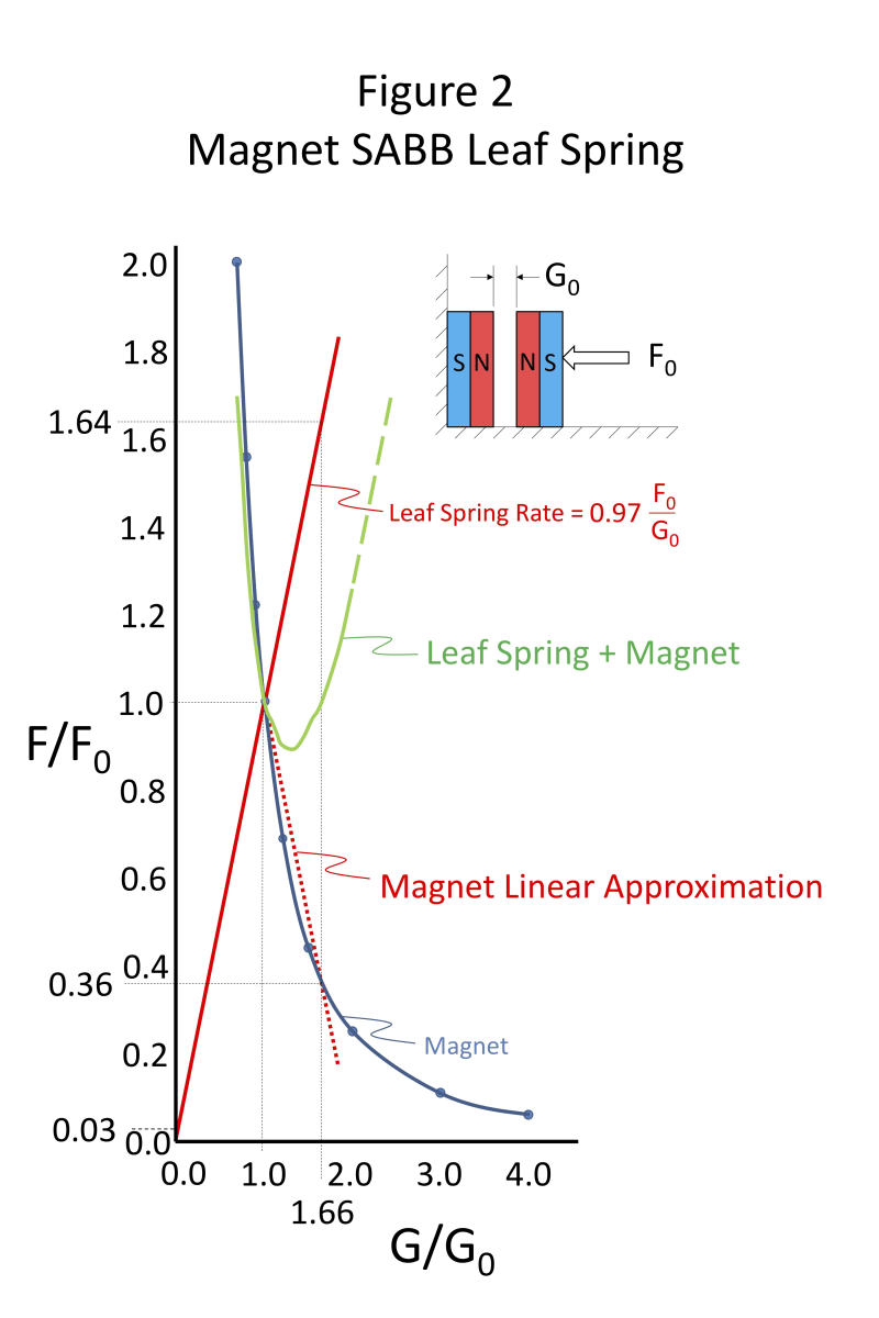
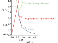
Figure 2 is a graph of ratios of the change in force F/F0 vs. change in gap G/G0 for a Permanent Magnet SABB in which the springy element is, for example, a leaf spring. G0 is the initial gap between the Bearing Segment Magnets and Shaft Magnets, and F0 is the initial magnetic repulsion force at Gap G = G0. The figure shows how the repulsion force ratio Fm/F0 of the magnets falls off as the inverse square of the change in gap ratio G/G0. The figure shows that the magnetic force ratio Fm/F0 is approximately linear from G/G0 =1 to G/G0 = 1.66 such that a Leaf Spring could be designed with an Fs/F0 vs. G/G0 relationship that mirrors the Fm/F0 vs. G/G0 of the magnets such that the combined magnetic and Leaf Spring force (Green curve) is dynamically stable.
The Slope (SMagnet) in the linear approximation region of the Magnet Force Fm vs gap G from G/G0 =1 to G/G0 =1.66:
1) SMagnet = ∆(FMagnet/F0)/∆(G/G0)
= (0.36-1.00)/(1.66-1.00)
= - 0.64/.66
= - 0.97
The Slope (SSpring) of the Spring Force Fs vs. gap G is the mirror image of the slope of the Magnet Force Fm vs gap G:
2) SSpring = 0.97
3) SSpring = ∆(FSpring/F0)/∆(G/G0) = 0.97
Solving 3) for ∆ FSpring/∆G:
4) ∆FSpring/∆G = 0.97 (F0/G0) = KSpring
5) KSpring = 0.97 (F0/G0)
The use of magnetic force in bushing bearings to keep the rotating parts from contacting each other has many advantages:
- Essentially no friction.
- No wear of mating parts.
- No failures due to loss, degradation, or contamination of lubricant.
- No increased wear at start-up (before the contact surfaces are fully lubricated).
- Essentially no change in friction due to changes in temperature.
- Can accommodate non-magnetic contamination.
Applications include: wind turbines, gas turbines, gyroscopes, fans, fidget spinners, pumps, electric motors, etc.
Like this entry?
-
About the Entrant
- Name:Douglas Larson
- Type of entry:teamTeam members:Tom Danowski
Doug Larson - Software used for this entry:SolidWorks
- Patent status:pending