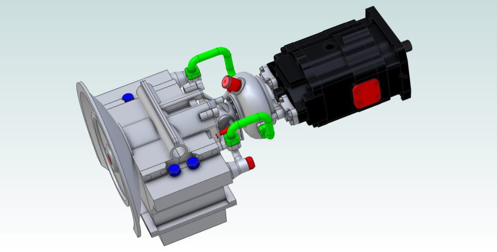


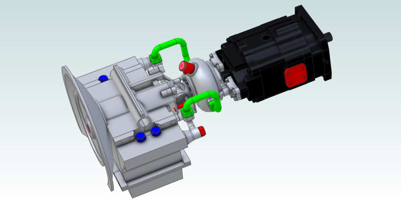


Presented in Fig 1 is an overview of a Constant Speed, Infinitely Variable Semi-tractor transmission which utilizes an Angular Motion Translator (AMT, US 6,547,689) to control a Variable Displacement System (VDS, US 9,890,638) (or Hydraulic Pump) coupled to a Hydraulic Motor.
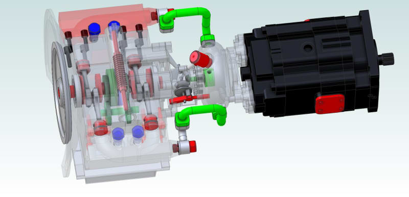
The Variable Displacement System (see Fig. 2) consists of an in-line, co-axial, dual-crankshaft assembly with the fore and aft crankshafts each driving a pair of piston assemblies. In Fig. 2, the pistons to the left (near) side of the transmission form one pair with a common headspace, and the pistons to the right (far) side of the transmission form another pair with their own common headspace.
The Angular Motion Translator resides between the fore and aft crankshafts and permits the power input to the flywheel to be transmitted through the fore crankshaft, and through the AMT, to the aft crankshaft. Additionally, the AMT allows an additional 180° of angle to be added to (or subtracted) from the aft crankshaft while the transmission is under load.
The forward Annulus Gear of the AMT (the green annulus Fig. 2) is held static (non-rotating) by a force sensor which allows for monitoring instantaneous torque. The aft Annulus Gear of the AMT (The light purple annulus in Fig. 2) is driven by the worm-gear break that allows for injecting an additional 180° of rotation into the aft crankshaft. The worm-gear break would be driven by a servomotor which in turn would be controlled by a computer programmed to adjust the displacement of the system to hold the Internal Combustion Engine at its most efficient speed (RPM).
When the pistons are in-phase, Fig. 2, the maximum amount of hydraulic fluid will be drawn through a pair of suction check-valves from the reservoir as the pistons move to the bottom of their common headspace/cylinders. Then as the pistons move in phase toward the top of their common headspace/cylinders, they discharge the maximum displacement through their common discharge check-valve.
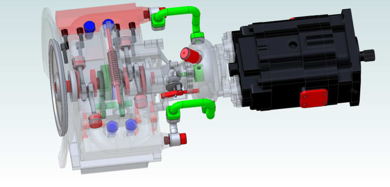
As shown in Fig. 3, as the AMT has added an additional 180° of motion to the aft crankshaft while under load, the paired pistons are completely out-of-phase. In this state, the fluid within the common headspace/cylinders will simply moves back and forth between the common cylinders; no additional fluid will be drawn in from the reservoir, and no fluid will be discharged through the common discharge check-valve.
Between these two limits of the completely in-phase state of the paired pistons, and the completely out-of-phase state, an infinite number of states can be established by adjusting the worm-gear brake. This will therefore perform as a transmission with an infinite number of gear rations.
As fluid is discharged from each common headspace/cylinders through their respective discharge check-valves, it first is routed through a damping chamber before passing through a reversing valve assembly to the ports of a Hydraulic Motor.
This apparatus will pass 1600 ft-lbs. of torque to the driveshaft of a semi-tractor rig, generating 640 horsepower at 2100 RPM, and can accommodate most available diesel engines.
Like this entry?
-
About the Entrant
- Name:Paul Baker
- Type of entry:individual
- Software used for this entry:AutoCAD, Alibre Design, SimWise
- Patent status:patented