


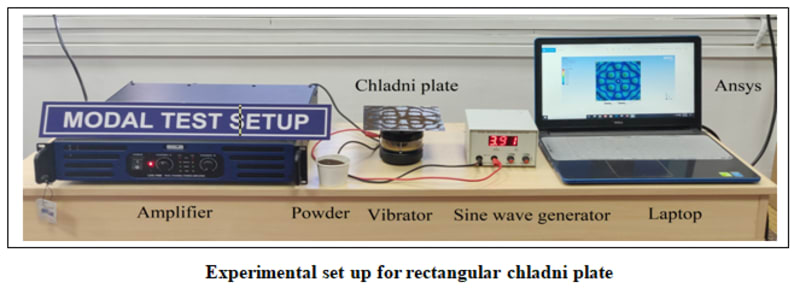


Ernst Florens Friedrich Chladni was a German physicist and musician. His most important work, for which he is sometimes labeled as the father of acoustics, included research on vibrating plates. Modal analysis is used to find out mode shapes and natural frequencies of system. This work aims at demonstrating nodes and antinodes at various frequencies of vibrations. Chladni plate is used for this purpose. When the plate is excited because of vibrations from a vibrator source, the sand of the plate creates specific patterns. These patterns are related to the excitation frequency. The sand on the plate moves away from antinodes where the amplitude of the standing wave is maximum and towards nodal lines where the amplitude is minimum or zero, forming patterns known as Chladni figures. The formation of patterns depends on material properties, geometry of plate, and thickness of plate and frequency/vibration pattern of the vibrator. The experimental setup consisted of a aluminum rectangular plate of 16 cm × 16 cm thickness of 0.61 mm placed over a mechanical vibrator (GelsonLab HSPW-003), which was driven by a sine wave signal generator (Ningbo Hema scientific). The procedure consisted in sprinkling powder on the plate and sweeping the frequency of the function generator until a constant pattern was obtained. Different shapes formed by sand particle on the plate at different frequencies will be captured by the camera. Validation of experimental work is done with ANSYS mechanical software.
Above methodology can used for motor and IC engine. We can attached chladni plate setup on motor and IC engine for fault detection. For example, Motor is running on some RPM.
ω = (2ΠN) /60. From this mathematical expression we can calculate the frequency. This will be excited frequency. Particular mode shapes will be associated with particular frequency. We can benchmarking of mode shapes for particular frequency. after that we crated fault in motor teeth. then we observed mode shape varied from bench marked mode shapes. Now we can conclude that our motor is facing some problem or fault in motor. This is cheaper way to find out to fault detection in motor based on mode shapes formed on chladni plate is attached on motor. Same methodology and approach can used for IC engine for fault detection.
Next step, we can introduced machine learning for image recognition. Image processing basically includes the following three steps- Importing the image via image acquisition tools, analyzing and manipulating the image and Prediction in which result can be altered image or report that is based on image analysis. Accuracy of machine learning program drastically increases by adding edge detection and grey scale algorithm. For machine learning program required more number of data as we captured more images in different classes for machine learning.
Like this entry?
-
About the Entrant
- Name:Atul Kumar
- Type of entry:individual
- Software used for this entry:Ansys mechanical and Ansys SpaceClaim
- Patent status:none