


Has the sound of the oil truck backing into your driveway ever scared you? How about waking to find no heat in the house because you ran out of oil. How many people reading this can say how much oil they have, without going down to the basement, garage or outside? Neither can I. My house was built in 1959, a relic of the Cold War, complete with a bomb shelter. The shelter is no longer used for its' intended purpose, but houses my two oil tanks. Checking the oil level is difficult for me, and impossible for my wife, due to her disabilities. So, my goal was to design and build a level sensor that can be viewed remotely, by my wife.
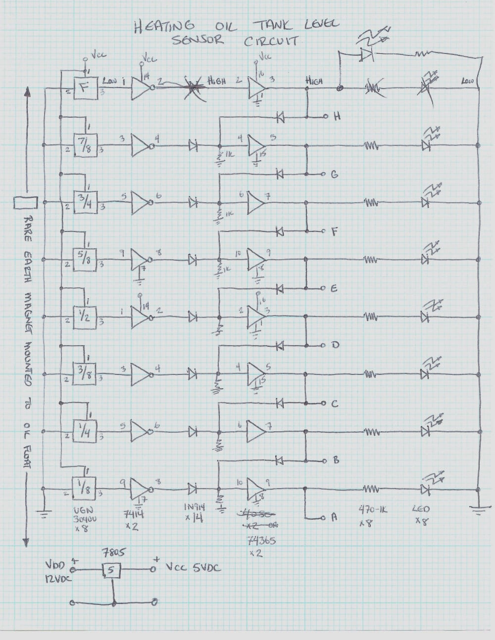
The most cost effective solution was to adapt the existing float type level gauge to an electronic readout. I decided on adding a magnet to the float indicator disk, and use that to activate some Hall Effect type switches. I located some surplus non-latching Hall Effect switches, UGN-3040U made by Sprague Electric, now known as Elegro. There are 8 switches used, to indicate tank levels in eights. The UGN-3040U switch has a low voltage output when sensing a magnetic field of sufficient strength. The circuit I designed, sends this output through and inverter stage, and then through a buffer stage. The output from the "Full" buffer is sent to the input of the "7/8" buffer via a 1N914 diode. The inverter outputs are isolated from the buffer inputs also by the same type 1N914 diode. This arrangement allows for cascading the stages to allow for a "filled in" looking bargraph, when only one switch is activated by the magnet.
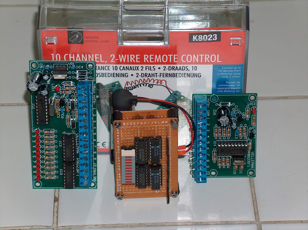
The last part of the design was to transmit the display from the oil tank location, to a remote location in the living are of the house. I chose to use a readily available Velleman brand K8023 10 Channel to 2 Wire Remote Controle. Basically, what is sent to the inputs is transmitted to the output display.
The K8023 could not be used directly with my level sensor design. A interface circuit had to be created that would make a low input to the K8023S'1. I inverted the outputs from the buffer stages and sent the outputs of the inverters to the inputs of the K8023S'1. The Velleman kit has 10 inputs, so the other 2 can be left unused, or use then to indicate the level sensor is powered up. I am using the latter idea.
So far, after about 100 feet of 2 wire cable used, my display is working, and my wife can be at ease we are not out of oil, and it is not too early for a new oil delivery.
Like this entry?
-
About the Entrant
- Name:Jason Kascenska
- Type of entry:individual
- Hardware used for this entry:Pad & PenSoftware used for this entry:Brain
- Patent status:none