
Control system software testing is done to determine if a program will correctly meet its specifications and not perform unintended functions. For machinery OEMs, large portions of the software testing process are completed during machine commissioning. New machinery is often a multi-vendor effort between the machine builder and other machinery vendors or electric drive suppliers. Each vendor manufactures their equipment independently at their own facility, so only limited software interface testing is done between the systems. On the other hand, when machinery is rebuilt, one or more sections of the existing machine are replaced by new equipment. In this case, some of the machinery is already in place on site and is unavailable for testing. Either way, there is limited opportunity to test the integration of the new software with other new or existing equipment before commissioning. Unfortunately, during machine commissioning, production is shut down and financial pressures limit the time available for testing. Delays caused by software errors are costly to the customer and solutions are often hastily implemented in order to speed commissioning.
This solution is to use real time dynamic simulation to model machinery that is unavailable for testing. This allows control system software to be tested before new machinery is installed. It can also be used to train operators before installation so they are more familiar with the new equipment and also aware of how to recognize and handle faults.
The simulator consists of a programmable logic controller (PLC) or personal computer (PC) that that is capable of solving differential equations in real time to model the dynamic behavior of the machinery, electric drives, and process. The computational capabilities of modern PLCs/PCs have made it possible to use one computational device for both the machine control system under test and the simulator.
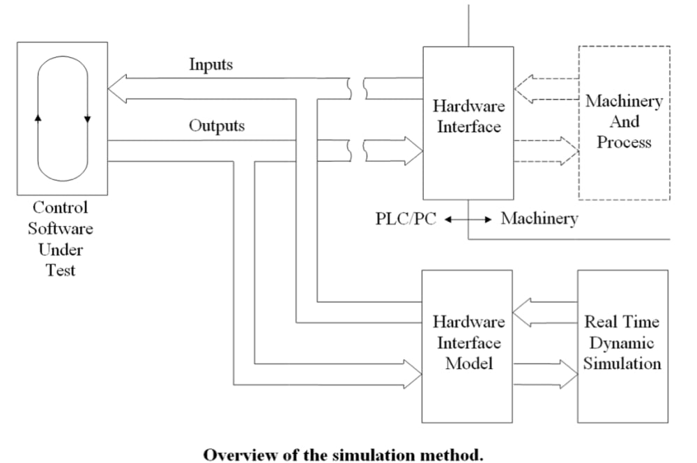
In normal operation, the state of the machinery and process is returned as inputs through a hardware interface to the program in the PLC/PC. The program is continuously cycling and processes the inputs to generate commands. The new commands are sent as outputs to the machinery through the interface.
When machinery is unavailable, a mathematical model of it is formed consisting of a system of ordinary differential equations. This system of equations is then programmed into the PLC/PC and solved using a simple constant step size numerical integration method. The solution of the dynamic model is done in real time i.e., the simulation time is scaled to correspond to actual time.
The attached figure shows that the simulation of the physical system is done in the same PLC/PC in which the control software is implemented. This reduces the amount of hardware required for testing and reduces the development time and costs of the simulation.
To implement the simulation, the signal path between the control software and the hardware interface is temporarily broken as shown in the figure. The model is then inserted into the signal path to generate the appropriate inputs for the control software based on the outputs.
Like this entry?
-
About the Entrant
- Name:Bob Bettendorf
- Type of entry:individual
- Hardware used for this entry:PLCs and PCsSoftware used for this entry:Allen Bradley ControlLogix programming software
- Patent status:none