


The swimming pool is an American icon for summer fun. Leaving the house and the pool unattended can sometimes lead to unpleasant surprises. I have had a few myself, which led me to develop the swimming pool pump controller. Based on my own experiences, I decided the controller needed to have the following features:
1. Turn off the pump when very low filter pressure sensed.
2. Turn off the pump when very high filter pressure sensed.
3. Turn off the pump when rated motor temperature exceded.
4. Turn off the pump when a water leak is sensed at filter.
5. Automatic restart from a power failure / restoration.
6. Manual shutoff (EMergency Off) provision.
7. Manual restart (Reset) provision.
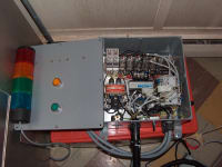
8. Visual status indication via a light tower.
9. Provision for a remote EMO and Reset for disabled folks.
10. A maintenance feature to indicate sporadic problems.
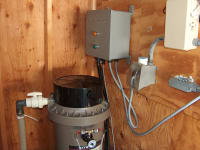
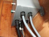
The controller system adds two pressure switches at the filter tank pressure gauge. One switch is NO for low pressure, and the other is NC for high pressure. Typical pressure is between 5-20 psi, for normal operation. A NC thermal snap switch monitors the motor temp, matching the motor spec plate. The water sensing can be just a leak sensor, but can also incorporate an optional pool water level sense, shutting off when too low, and alarming when too high. The controller would turn itself on when the standard external timer turns on, and this will also work with a power failure. Manual pushbutton switches are provided to shut off the pump motor at will, and restart from a failure or EMO. The light tower is used to visually indicate the status of the controller. Normal operation is, Yellow turns on when the controller first starts the pump, and there is momentarily no pressure. The Green light then comes on when the filter has correct pressure, and the yellow will extinguish. The Red light comes on when either the low pressure, high pressure, motor temp, or water sense inputs are tripped during normal operation. A blue light is added to indicate the controller is running in a maintenance mode, to keep the offending signal active for troubleshooting. This feature is activated by plugging the controller optional cable into a 120V convenience outlet. This is not normally done when the controller is powered solely by the external power timer. Installing this controller involves adding the two pressure switches as mentioned earlier, plugging the controller into the external timer outlet, and plugging the pump motor into the controller.
Mounting the light tower and the remote EMO would also be done as required or desired (Remote EMO not shown in illustration, remote connector provided on controller).
Like this entry?
-
About the Entrant
- Name:Jason Kascenska
- Type of entry:individual
- Software used for this entry:MS Excel
- Patent status:pending