
In this summary I try to briefly introduce the problem and a design for cheap photonic logic circuit proofing.
The problem.
Photonic Computing is the use of light to do computation. Via intensity modulating laser sources in order to get a binary representation of info onto a carrier. Thus for 5 data lines one could use 5 colors of light but imagine for a moment that we would want to do some logic on a 5 bit data stream. One would imagine that it would be as easy as directing the data through the photonic logic blocks. If the circuitry was small it might just work but for complex scenarios one would need to predict the logic level and wavelength in question of the output in order for the circuit afterwards to be designed to accept or manipulate that particular wavelength with the data modulated on it.
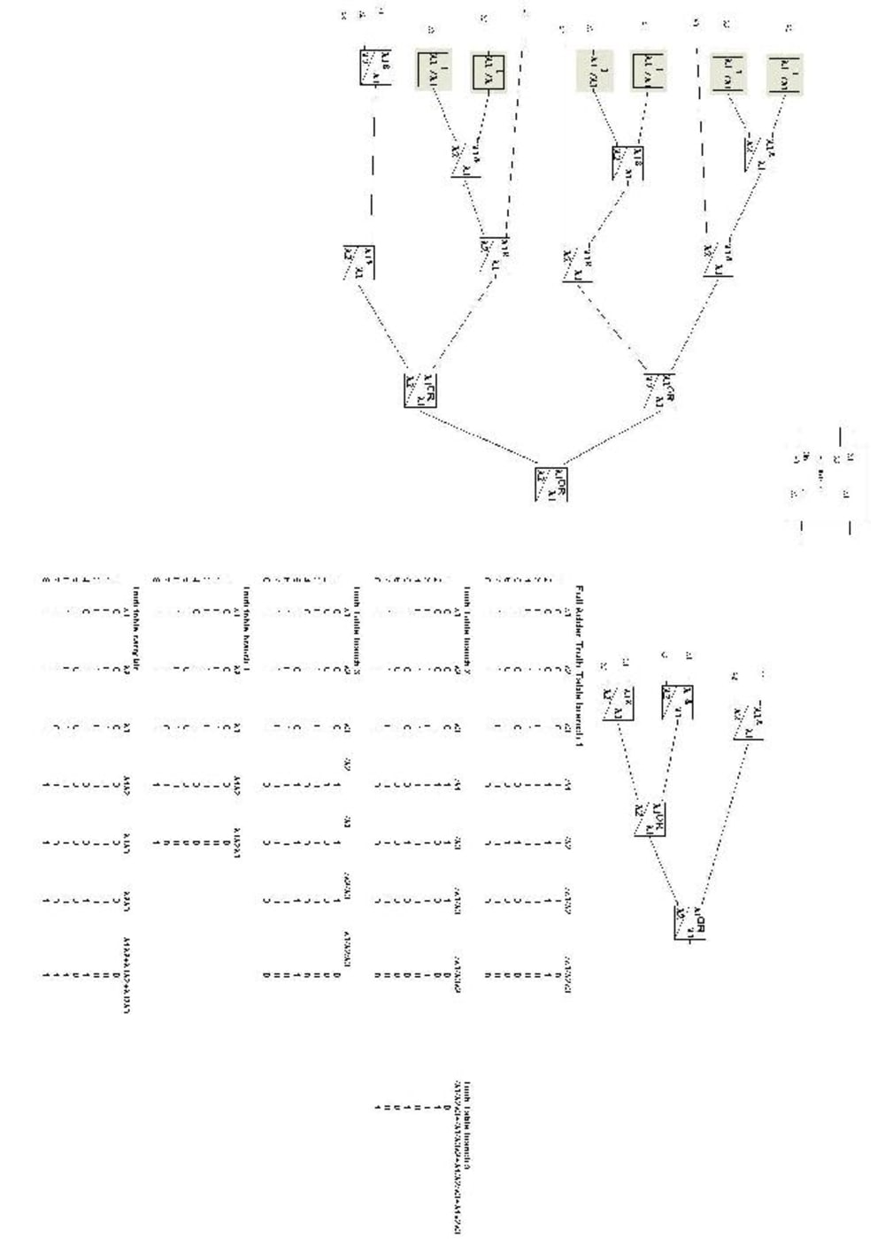
From the Figure a basic 2 bit photonic adder is shown. For this design to work each block has to be designed for optimal response to the particular wavelength of the stream in question. This means that before the individual blocks are attempted to be designed the wavelengths to which they will see has to be considered.
The solution
This design will only give the theoretical (ideal) logic level and the wavelength information as we strive to achieve the ideal.
Firstly the blocks used in this design are inverter, and gate, and or gate. Just imagine each block having a ports (input / output) and these ports are connected through links and for each block it has a structure determining its properties for instance for an and gate it may need.
struct logic_gate{
int input_wavelength1;//wavelength,number
int input_wavelength2;//wavelength,number
int input_level1;
int input_level2;
int output_level;
int output_wavelength;
int time_ref;
}and;
Now from theory on photonic AND gates there is a wavelength conversion done in the circuit as well as AND logic. Its assumed that for the block level that whatever input wavelength is on port 1 of an AND gate the output will be on that particular wavelength. Hence if the input 1 is wavelength 1 with a 1 modulated onto it and the input 2 is wavelength 2 with a 1 modulated onto it the output would be wavelength 1 with a 1 modulated onto it. This example is simplistic but just imagine simulating complex circuitry with optical buffers wavelength converters as well as a list of other logic gate mappings how would one go about simulating such scenarios.
From above each block is assigned a port and each block would reside in a linked list and this may be a niave approach but for every circuit the output is calculated via traversing the list and determining the inputs and outputs via the ports and linkage information. Thus one can envisage a setup such that one could optimise circuitry via designing out wavelength converters and thus reducing complexity of circuitry. My proposal is to write a program in c++ to achieve this.
Kind Regards
Michael Cloran
Like this entry?
-
About the Entrant
- Name:Michael Cloran
- Type of entry:individual
- Software used for this entry:Linux C++ Photonic Theory
- Patent status:none