


The invention can be used in designing complete autonomous power installations for stationary applications(up to 5MW) and for mobile applications (up to 1MW).
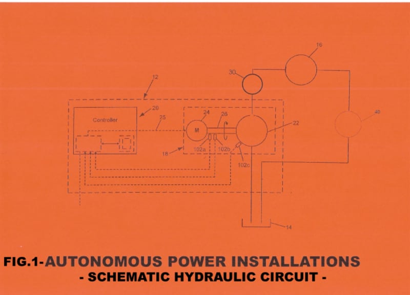
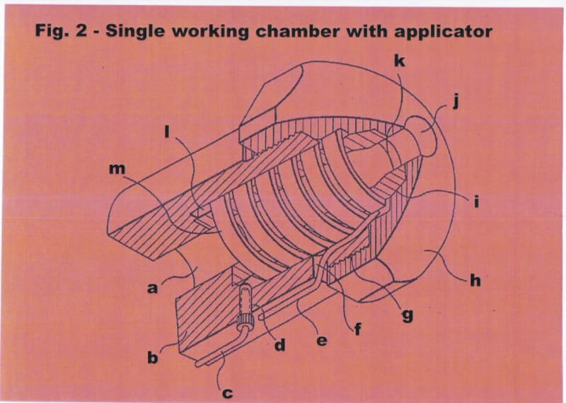
According to the proposed principle and methods for performing self-sustained power installations (fig.1), the working fluid (water,water-based fluids, bio-hydraulic oils, etc.) is delivered from a liquid reservoir (14) by a liquid feed pump station with overflow hydraulic valve under low pressure through a filter ,and through flow control hydraulic valves assembly into working chambers (fig.2) of the pressure amplifier block (30) provided with various applicators which are forming various energy fields. High pressure (up to 700bar, function of the working fluid) is created in the working chambers of the pressure amplifier block by passing strong and fast pulses to applicators placed internal, external, or internal and external relative to the working chambers. The pulses are supplied to applicators from a generating unit by means of a system with a rechargeable power supply (the rechargeable power supply is used just for starting and process activation), with electronic control. The strong and fast delivered pulses and various created energy fields (coupled multi-physics phenomena) are forming high-pressure liquid-phase volumes and are forcing out liquid from the working chambers which is supplied through flow control hydraulic valves assembly to hydraulic actuator(s) (16) (rotary or rotary and linear actuator(s)). Instantaneous, based on relaxation of the liquid-phase volumes and reduction of the pressure in the working chambers, the chambers are filled with the working liquid through flow control hydraulic valves assembly under low pressure (up to 100bar) by the liquid feed pump station (22). The pressure in the working chambers is regulated by electrically overflow hydraulic valves by signals from pressure transmitters installed in the working chambers.
The system (liquid-phase cycle) to implement the principle and the methods consists of a liquid reservoir (14), liquid feed pump station (22) coupled to an electric motor (24) supplied by a system with a rechargeable power supply, feed pump station fluidly connected through flow control hydraulic valves assembly with input of working chambers, output(s) of the working chambers is (are) fluidly connected through flow control hydraulic valves assembly and high pressure pipe(s) with input(s) to the hydraulic actuator(s) (16) (which can produce at least two times more power that is operationally consumed by the feed pump station, the valves assembly, the pressure amplifier block and the cooling system together) ,the hydraulic actuator(s) is being coupled to electrical loads(for stationary applications) or to electrical and mechanical loads (for mobile applications).
From the hydraulic actuator(s), the working liquid flow through intermittent cooling system (40) to a liquid feed reservoir. The entire system is controlled by a signal control unit (20). In one embodiment, the feed pump station and the cooling system can be placed on a secondary line of the principal circuit. In another embodiment, the feed pump station coupled to the electric motor is replaced by advanced pump stations with no moving parts and low power consumtion.
The rotary hydraulic components(pumps,actuators) can be of the type hydrostatic, and/or hydrodynamic.
CONCLUSION: "Clean" and safety electrical and mechanical power can be obtained with power net efficiency (PNE) of the liquid-phase cycle greater than 1 ((PNE=Pha/(Pps+Ppab+Pva+Pcs)-1)>1,where: Pha-hydraulic actuator(s) generated power, Pps-pumps station consumed power, Ppab-pressure amplifier block consumed power, Pva-valves assemblies consumed power, Pcs-cooling system consumed power).
Like this entry?
-
About the Entrant
- Name:Rabei Romulus
- Type of entry:individual
- Software used for this entry:MATLAB+SIMULINK,ANSYS+FLUENT,SIMERICS
- Patent status:patented