


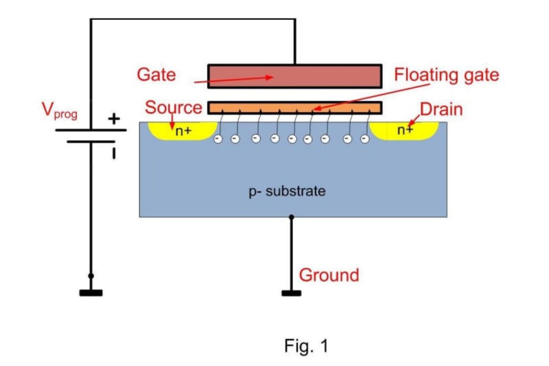


The invention principle of work is based on the quantum mechanics phenomena - electron tunneling through potential barriers. The process is well mathematically modeled by the Fowler-Nordheim formula. It is used for storing of the information in the EEPROM cells, where special FET transistors called FGMOS (Floating-Gate-Metal-Oxide-Semiconductor) serve this purpose.
If the drain and source (terminal names of the FET) are connected to the ground and high voltage Vprog is applied at the gate (the third terminal) – a tunneling electron current flows and charges the floating gate (Fig.1). It can reach 10A/meter square density.
Let us connect millions /billions of FGMOS’s in parallel:
1. All sources and drains are connected to the ground.
2. All floating gates are connected in one network
3. All control gates are connected together.
Let us simplify the whole system by use of the capacitors - three main capacitors can be distinguished (Fig.2):
1)Ccg-fg – between the control and the floating gate
2)Ccg-gp – between the control gate and the ground plate
3)Cfg-gp – between the floating gate and the ground plate
The Quantum battery comprises three metal (semiconductor) plates: Injector (Anode, Ground plate), Cathode (floating gate) and Control plate. They all are placed in parallel to each other at some distance between themselves in a form of a sandwich. The Cathode is in the middle. Between the Cathode and the Injector is placed a thin dielectric layer. Between the Cathode and the Control plate another dielectric layer with thickness higher that the first one is placed. All plates and layers have physical contact. The Quantum battery comprises also a standard high voltage source (>=15V), with cathode connected electrically to the Injector and anode connected to the Control plate. The Injector and Cathode plates of the Quantum battery are wired to the corresponding output terminals of Quantum battery.
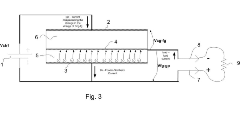
The principle of work of the Quantum battery is explained below:
When the high voltage battery 1 (Fig. 3) is connected between the Injector 3 and the Control plate 2 the current Ifn starts to flow. It starts to charge negatively the capacitance Cfg-gp. A current Igc from the HV battery flows to compensate the potential change at the Cathode.
Igc=Ccg-fg*d(|Vctrl|+|Vfg-gp|)/dt
Let us when the voltage Vfg-gp reaches some desired value Vbat connect a resistive load 9 between the Injector and the Cathode. The resistance value R is set so, that the load current Iload=Vbat/R is equal to Ifn. Then all electrons tunneled from the Injector to the Cathode, will go in the load. The charge of the three capacitors will remain constant. Vbat will be also constant. The voltage Vcg-fg will as well. The current Igc will not flow. No power will be consumed from the high voltage battery, but energy will be dissipated in the load. It sounds like perpetual machine, but the trick is that before and after the tunneling the electrons have the same energy and no energy is needed from the external source.
Contact: penev_milen@yahoo.com
Like this entry?
-
About the Entrant
- Name:Milen Penev
- Type of entry:individual
- Software used for this entry:MS Word :-)
- Patent status:pending