


"Synergistic Magnetic Drive System"
Inventor: Dr. Thomas P. Walker, Jr of Bogosh Walker Technologies
Electronics Engineer: Francis Flexer, Jr
Fabrication Engineer: Brian Dougherty
Purpose:
To cause movement of a cylinder containing Neodymium Magnets in a configuration, pattern and level of force that allows the simultaneous pushing and pulling of other magnets in a semi-synchronized state. The end result would be a moving shaft to connect to anything that requires a rotational force, motion, torque and control of same.
Simplified description of physics:
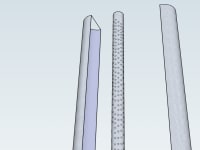
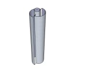
The central shaft contains a specific and proprietary pattern of NdBeB magnets with polarities and level of force. Set so as the outer controlling magnet induction system is engaged, the central shaft is pushed/pulled with the pattern of magnets contained in. (see Figure 1) This is controlled by the fields of the magnets as they are moved closer or further from each other. An increase or decrease of force applied between the magnets will increase the spin rate or allow declaration by moving the fields apart. Also note that the magnetic induction control system is not completely parallel when in the closed position. (see Figure 2)
The central shaft is constructed of non-magnetic or low-magnetic properties and can withstand spin rates of 0 to 7000 revolutions per minute either terrestrial or non-terrestrially respectively. The outer magnet induction assembly contains the partial inverse state of the magnetic pattern, polarities and level of force of the central shaft. It is comprised of non-magnetic or low-magnetic material.
The shape of magnets reflect the magnetic field properties such as shape of the field the magnet possesses. Certain shape magnets are more conducive to positioning on a cylinder with holes cut to fit the magnet shape and positioning requirements.
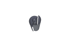
The bearing assembly is comprised of high Tesla, cylindrical Neodymium Magnet with the center being hollow. The magnetic polarity is the center portion of the cylinder is NORTH and the outer jacket is SOUTH. The end of the central shaft listed above is fitted with a high Tesla, cylindrical Neodymium magnet with the center of the cylinder being hollow. The magnetic polarity is the center portion of the cylinder is SOUTH and the outer jacket is NORTH. Self centering and high speed bearing system with virtually undetectable frictional force. (see Figure 3)
Target Market:
Electricity generation system which feeds capacitor storage network for electrical power requirements in either a terrestrial or non-terrestrial environment. There are already companies working with NASA on the electricity storage system.
Any device that requires controlled rotational force and torque.
Closing:
There are others working with similar ideas. I just figured out the required pattern to produce the physical force needed to move an object utilizing the stored and slow dissipating energy of the magnet. The Team is here to produce usable units for market.
Please forgive the crude images attached with this. 3D rendering is not my best thing.
Thank you for your time.
-Dr. T. Walker, Jr & Team Bogosh Walker Technologies
Like this entry?
-
About the Entrant
- Name:Thomas Walker
- Type of entry:individual
- Software used for this entry:Open Source
- Patent status:none