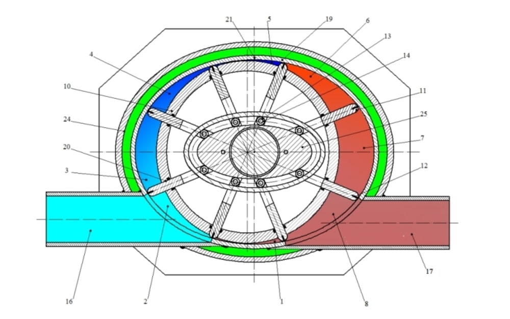

The engine consists of an elliptic casing 19, a rotor 10 with vanes 11 that, owing the copy mechanism 25, allows them to maintain contact with the elliptic casing in all positions. So the vanes play the role of the pistons. A single vane replaces one piston, one cylinder, few valves, connecting rod; there is no need for a cranck shaft, cam shaft… The vanes are joined together by joints to the copy mechanism 25 by means of a small rod 14, a wheel 13, an elliptic casing 9 with an intake channel 16 and an exhaust channel 17. Between the casing, the rotor and the two adjacent vanes, the eight variable rooms 1,2,3,4,5,6,7 and 8 of different volumes are formed. The ratio of the volume 3 and the volume 5 is the compression rate, while the ratio of volume 7 and the volume 5 of compression is the expansion rate. With an appropriate ellyptical design of the casing and a copy mechanism for moving the vanes, and with an eccentric position of rotor axes towards the copy mechanism axes, the any required compression ratio and a significantly higher (over) expansion rate can be achieved. This allows us to achieve a very high power efficiency. As opposed to Wankel engine this allows an application of Diesel process, too. The rotation of the vanes causes them to automatically open and close the intake and exhaust channels, so there is no need for any additional mechanisms that will open and close them. The symmetric design of the rotor with vanes provides the best balance of the motor and enables a great rpm number, as well as greater power per unit of weight. The lower fuel consumption makes it possible to use various types of fuel, with a lower exhaust gas temperatures and lower content of harmful components, resulting in a dramatic decrease of noise and achievement of special ecology and energy benefits. To top it all, the simple design results in low production cost, which provides a significant advantage for this invention as opposed to solutions known to date.
By turning the rotor, the room 3 fullfiled by intake air, untill the position of room 4, comes to the position of the end of compression in room 5. This is where ignition of the compressed air (or mixture) is conducted by a flow of fuel (or spark-plug) 21 imbedded in the elliptic casing 10. Ignition of the mixture increases the pressure inside room 5, pushing the vane 11 into position of room 6, thus creating the torque and expansion when arriving at the position of room 7. Further rotation of the rotor, the vane 11 opens the exhaust channel 17 and initiates the exhaust through the position of room 8 until it again reaches the position of room 1 which is the end of exhaust and beginning of the intake. After the intake in position 2, the starting position 3 is reached and the process is repeated.
Like this entry?
-
About the Entrant
- Name:Damir Jelaska
- Type of entry:individual
- Software used for this entry:Auto-Cad
- Patent status:pending