


MECHANICAL SEALED GLAND VALVE
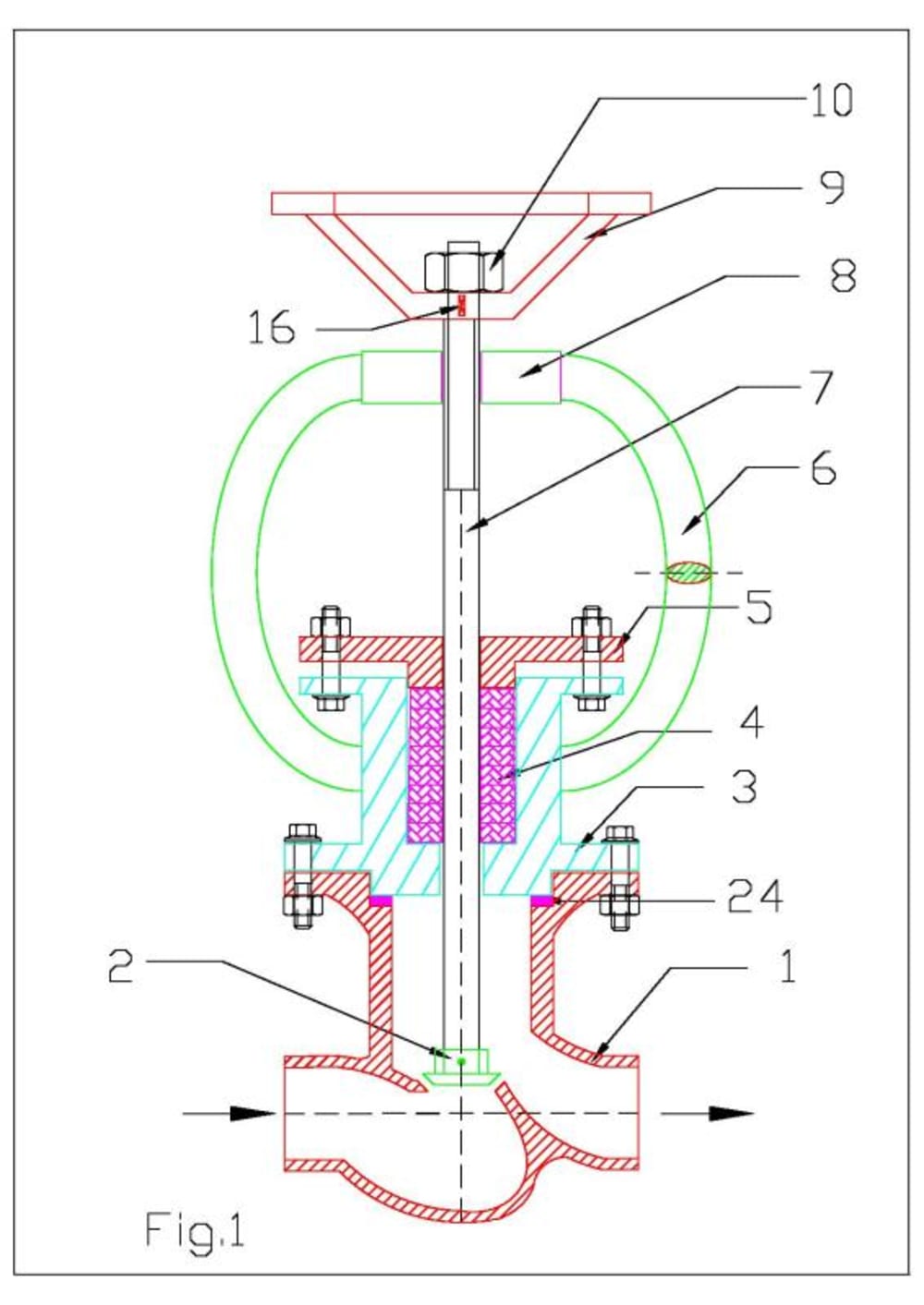
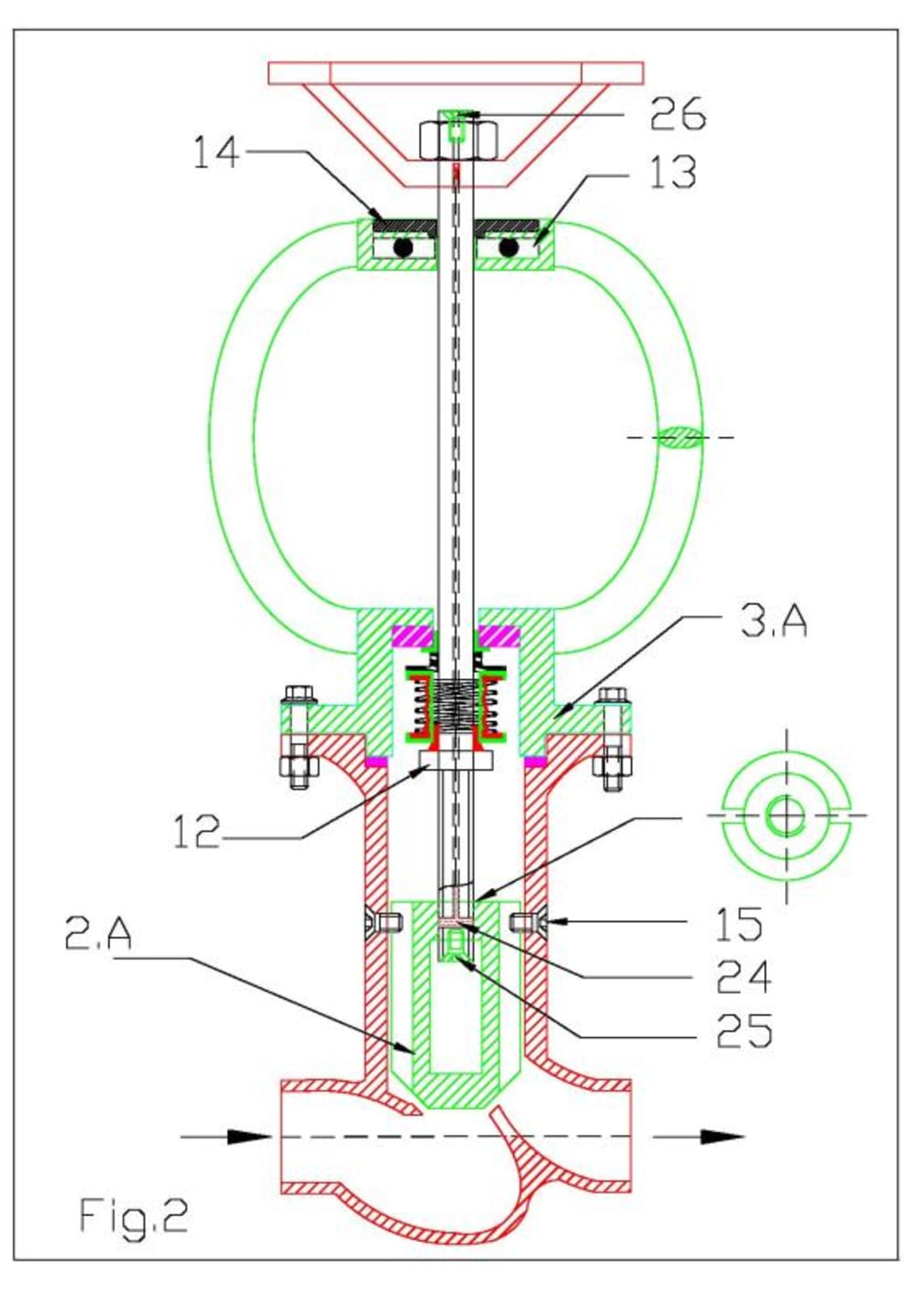
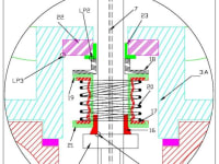
Three figures viz. Fig.1, Fig.2 & Fig.3 are attached. Fig.1 shows a typical globe valve with gland rope arrangement. Fig.2 shows a globe valve with a typical mechanical seal arrangement in lieu of gland rope arrangement. Fig.3 shows the magnified view of mechanical seal assembled inside the valve. Referring to Fig.2 and Fig.3, in which the gland rope arrangement is substituted by mechanical seal arrangement. The plug2.A is screwed to the valve spindle. Two vertical slots are made on the outer surface of plug whose top view is as indicated in the right side. Unlike the plug as shown in Fig.1, this plug does not rotate and can only move longitudinally up or down. Its rotary motion is restrained by the guide screws 15.When the handle is rotated, its rotary motion is converted into a linear motion of valve plug 2.A.
Sealing arrangement: The valve spindle has a step12 as shown the figure. The seal box 3.A is fixed to valve body1 by nut and bolt. Mechanical seal is assembled to the valve spindle above the step region. Above the step is the rubber bush 16 which fits tightly to the valve spindle. Above the bush 16 is metallic ring plate 21 which snug to the rubber bush 16. Above the plate 21, is bellow 17. The bellow is bonded to the ring plate by glue. Another metallic plate19 is glued with the bellow at the top as shown. The top of the metallic plate 19 is bonded with a rotary seal 18. A rubber bush 22 is tightly pressed inside the bore of seal housing 3.A. A stationary seal 23 is bonded to the rubber bush 22. The IDs of stationary seal 23, rotary seal 18 and metallic plates 21 and 19 are held with clearance with respect to spindle OD. Thus when the hand wheel is rotated the valve spindle rotates, the spindle step 12 also rotates in conjunction with bush 16, metallic plate 21, bellow 17, metallic plate 19, rotary seal 18 whereas stationary seal 23 & rubber bush 22 always remain stationary inside the seal box 3.A. Thus there is relative rubbing on seal faces of 18 and 23.The items 23 and 18 are super finished (lapped surfaces). The spring 20 hold the seal faces intact and automatically compensates for seal wear. A drilled passage is drilled through the center of the spindle with its end closed by grub screws 25 and 26. By opening screw 26 we can inject suitable lubricant oil for lubricating in between outside thread of valve spindle and inside thread of plug 2.A.
The mechanical seal is a better sealing arrangement and can be used for applications like toxic effluents, hazardous/flammable fluid, refrigerants, radioactive fluid etc. where leakage of fluid is not tolerable. Depending upon the application- nature of fluid, pressure and temperature, the components/materials of mechanical seal and design of mechanical seal has to be suitably made.
Like this entry?
-
About the Entrant
- Name:Ravi Paramanandam
- Type of entry:individual
- Software used for this entry:AutoCADD, Winword
- Patent status:pending