


Does anyone remember the incident when the Miami Heat “cheated” because a shot clock violation was called, even when the ball hit the rim?
This is why we need an automatic shot clock!
I know that this has already been invented by Spalding, but their shot clock has many problems, and its sales have not been successful because of this.
What was wrong with it?
-It did not sense net shots (swish)
-It picked up backboard hits, just as it would pick up rim hits
-Manual controls were difficult to reach
How did I solve it? I simply made a device that would
-Sense net shots with a laser beam
-Ignore backboard hits and only sense rim hits
-Have easily accessible manual controls.
How it works:
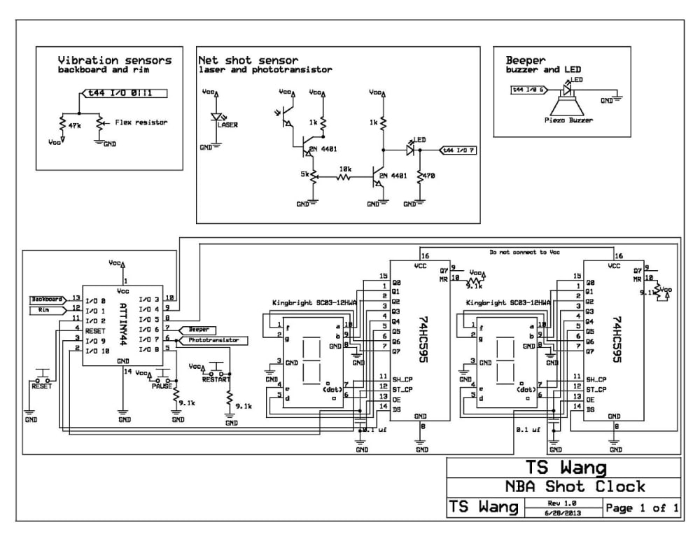
*Net shot sensor*
If the laser beam is blocked by the phototransistor, the microcontroller restarts the clock
*Rim hit sensor*
First of all, I am generating voltage from the two flex sensors. In flex sensors, the more you flex it, the more resistance it creates.
I have decided to use the flex sensors in a voltage divider. If you look at the schematic, you will notice that R1 (resistor to Vcc) is 47k, while R2 (resistor to ground) is the flex sensor.
The more the flex sensor flexes, the more resistance there is on R2, and more power can flow through R1. The more the flex sensor flexes, more voltage is let pass.
Let's look at an example:
SCENARIO 1: The ball hits the backboard
1) The backboard vibrates more than the rim
2) More voltage is passed from the backboard than the rim
3) The microcontroller compares the voltages.
4) If backboard resistance (voltage) >= rim resistance (voltage), do nothing
SCENARIO 2: The ball hits the rim
1) The rim vibrates more than the backboard
2) More voltage is passed from the rim than the backboard
3) The microcontroller compares the voltages.
4) If rim resistance (voltage) > backboard resistance (voltage), buzz and restart the shot clock
*Manual controls*
The manual controls are connected to the same I/O pins as the sensors. In the end, the I/O pin is only sensing whether that pin is HIGH or LOW.
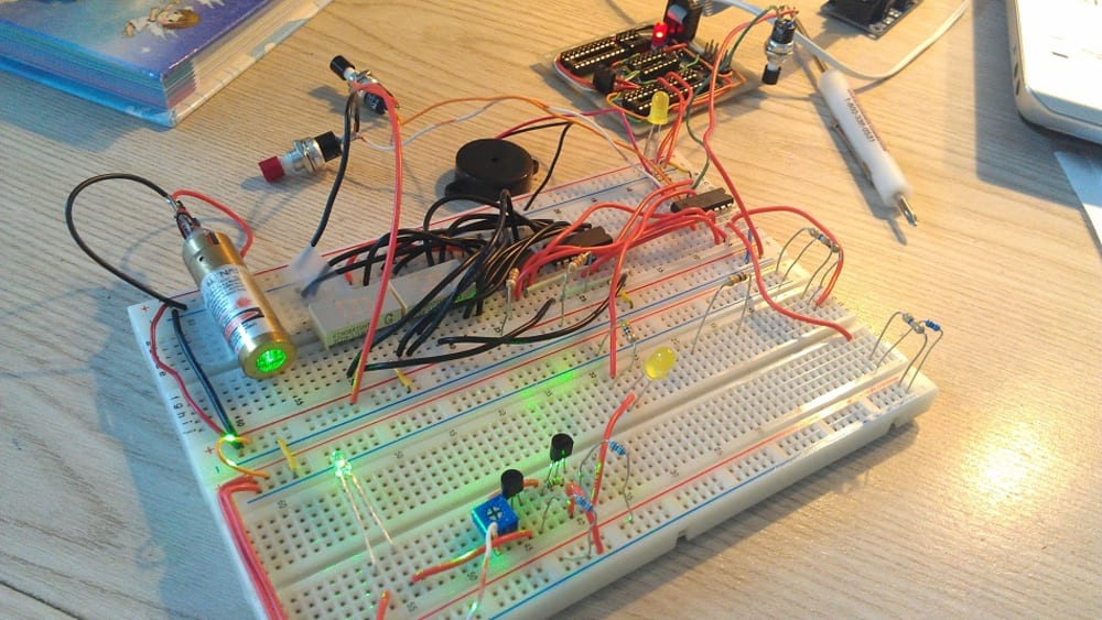
Currently, the device is working at its prototype stage. As soon as the missing parts are ordered, the prototype can be tested on an actual basketball hoop. In theory, on the breadboard, the device works just as I have expected.
After the prototype is finished and tested, I can begin to map out the circuit. The printed circuit board will be manufactured professionally.
The device will be assembled and packaged in separate enclosures - sensors will be separate from displays and separate from the device (see illustration)
I am hoping to sell this device to High School basketball coaches, intramural/college basketball courts, and maybe even professionals.
Detailed documentation and updates can be found at http://tswangshotclock.blogspot.com/. All documentation is free to be copied by the public and replicated.
Please watch the video to see how it works
Video
Like this entry?
-
About the Entrant
- Name:Jonathan Wang
- Type of entry:individual
- Software used for this entry:Arduino IDE, Microsoft Word, ExpressSCH, Vegas Movie Studio
- Patent status:none