


To improve the efficiency of internal combustion (IC) engines, an innovative Steam Assisted Co-cycle IC engine is invented. The working principle and prototype development of this new engine are introduced in the following.
WORKING PRINCIPLE
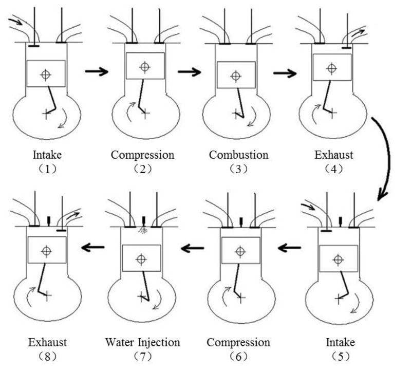
The working cycle of the steam assisted co-cycle IC engine is formed by one former cylinder and one later cylinder. The former cylinder works as a traditional 4-stroke internal combustion engine, while the later cylinder also works in the form of 4-stroke, however, without combustion. The exhaust gas of the former cylinder is transferred into the later cylinder to perform further work.
There are two working modes for the later cylinder, which are water injection and over-expansion.
In the high load condition, water is injected into the high temperature exhaust gas in the later cylinder to help the engine save energy. On one hand, the water could decrease the cylinder pressure in compression stroke to reduce the negative compression work. On the other hand, the water could evaporate into steam to push the piston power again in expansion stroke.
In the low load condition, for the exhaust gas temperature is not high enough to heat the water to work, the later cylinder works as an over-expansion cylinder without water injection. The exhaust gas could get further expansion in the later cylinder, because the expansion ratio of later cylinder is larger than the compression ratio of the former cylinder, which could improve the engine thermal efficiency according to the principle of the Miller Cycle.
PROTOTYPE DEVELOPMENT
The prototype engine was developed on a 4-cylnder 4-stroke gasoline engine. Cylinder 1# and 4# are the former cylinder, and cylinder 2# and 3# are the later cylinder. The firing time of two former cylinders are separated by 360°crank angle. The exhaust gas of cylinder 1# is transferred into cylinder 2#, and the exhaust gas of cylinder 4# is transferred into cylinder 3#. The exhaust valves of cylinder 1# and 4# open and close at the same time with the intake valves of cylinder 2# and 3# respectively. In order to simplify the exhaust gas transferring, the exhaust ports of former cylinder and intake ports of later cylinder were on the same side of the engine body. In this way, the exhaust ports of former cylinder and the intake ports of later cylinder can be connected just by an elbow pipe. The inlet and exhaust manifolds are both on the other side. The water injector was mounted in the later cylinder to inject water at the right time. Water is supplied by a high pressure water pump, which is just like the oil pump of a diesel engine.
Like this entry?
-
About the Entrant
- Name:Yong Lu
- Type of entry:teamTeam members:Pucheng Pei
Yong Lu - Software used for this entry:Pro-E, GT-Power
- Patent status:pending