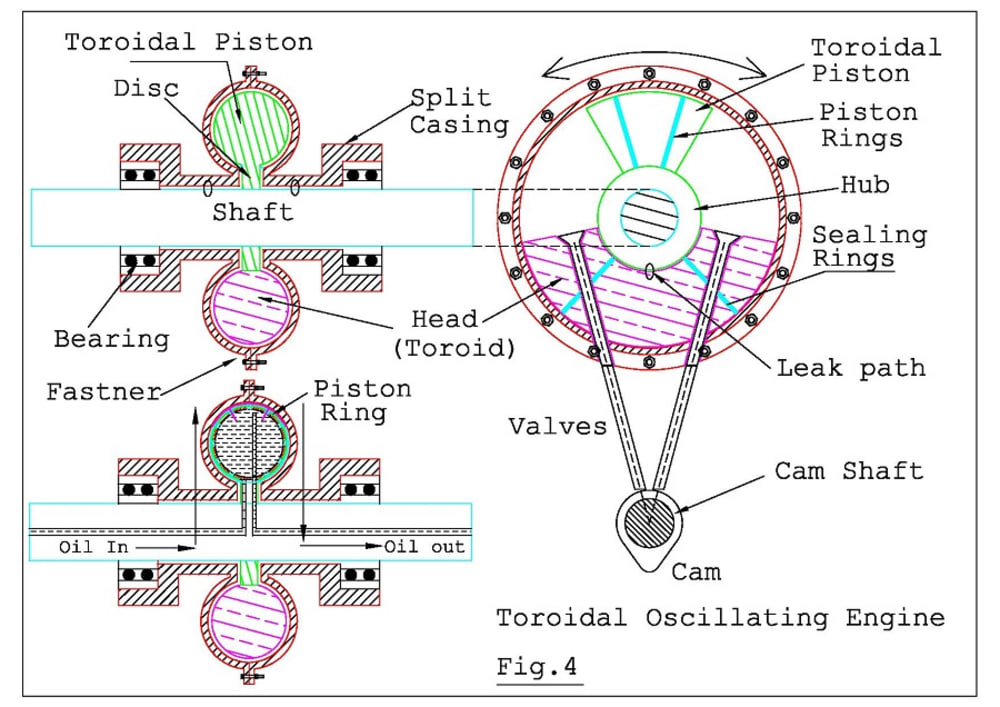


This proposal relates to a toroidal oscillating engine. Figure 4 describes the constructional arrangement. It has a sector shaped toroidal piston assembled with piston rings and joined to a circular disc/hub which is keyed to a shaft. The shaft is mounted in a split casing with bearings at both ends. A stationary toroidal head is rigidly fixed in the casing. The head houses suction, exhaust valves which are operated by a cam shaft and also houses spark plugs on the left and right side of the head. The engine is a double acting, four stroke engine in which the piston is shared in common. Engine initially produces an oscillating motion which is further converted into a rotary motion by a four bar mechanism as discussed below. The piston inner portion is hollow, lubricated as well as cooled by a pressurized oil circuit as indicated in the figure. There is a minute running clearance between the disc and head, shaft and casing which are marked by small circles and referred as leak path. The working of engine is shown in fig.3.
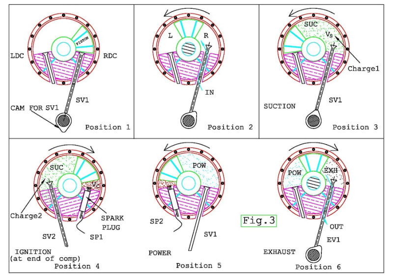
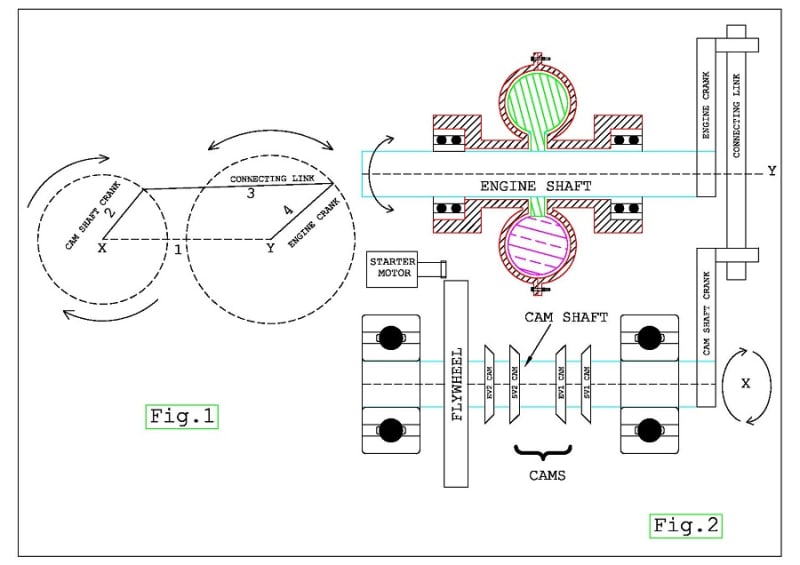
Assume the piston be in the Right Dead Center (RDC) as in Position 1. When the engine is cranked, the piston turns towards left and the Suction valve SV1 opens admitting the charge inside the engine. When piston reaches Left Dead Center (LDC) as in Position 3, it inducts a swept volume VS. Assume the piston again turns to right side. Now suction valve SV1 closes and the charge is compressed in clearance volume (VC). Nearing the end of compression the charge is ignited by spark plug SP1 as indicated in Position4 and power is produced which pushes the piston towards left as indicated in Position 5. Again when the piston turns towards right, the Exhaust valve EV1 opens and the combustion products are discharged out. A similar operation is simultaneously carried out on the left side also. Thus an oscillating motion which kicks the piston left and right is initially produced. Fig.1, briefs about a four bar mechanism. It has four links namely 1,2,3&4. To some particular lengths of the links, when link 2 is rotated fully, it causes link4 to oscillate. Its inversion i.e. conversion of oscillating motion into rotary motion is also valid, if the link lengths are suitably designed as per Grashof’s rule (Refer books on Theory of Machines). Now referring figure2, the engine delivers an oscillating motion as described earlier. The engine shaft is connected to a cam shaft having a flywheel at the end by a similar four bar mechanism. The engine link and flywheel link are suitably designed and connected by connecting rod link. Thus the oscillating motion from engine is converted into rotary motion of cam shaft and flywheel. As the engine is double acting, the engine weight per BHP is less. Piston ring frictional resistance/wear is less. As shaft is mounted in bearings, frictional resistance of shaft is insignificant. Counter weight opposite to piston shall be added for balancing.
Email: paravi59@gmail.com
Like this entry?
-
About the Entrant
- Name:Ravi Paramanandam
- Type of entry:individual
- Software used for this entry:AutoCAD
- Patent status:pending